Capacitors
Questions for Short Answer
1. Suppose a charge +Q₁ is given to the positive plate and a charge -Q₂ is given to the negative plate of a capacitor. What is the "charge on the capacitor"?
Answer: If we take the area of each facing surface = A, then the total area of each plate (both faces) =2A. The surface charge density of one plate = Q₁/2A and of the other plate =-Q₂/2A.
The directions of the electric field between the plates due to the charge on each plate are the same, hence they will add up.
So from Gauss law,
E = Q₁/(2Aε₀) +Q₂/(2Aε₀)
The potential difference between the plates, V =Ed, where d is the separation of the parallel plates.
→ V ={Q₁/(2Aε₀) +Q₂/(2Aε₀)}d
→V =(Q₁+Q₂)d/(2Aε₀)
→V =(Q₁+Q₂)/2C, (Since C=ε₀A/d) --(i)
Since the potential difference between a parallel plate capacitor having a charge Q is, V =Q/C,
Comparing it with(i), we get
Q = (Q₁+Q₂)/2, which is the charge on the capacitor.
2. As C = (1/V)Q, can you say that the capacitance is proportional to the charge Q?
Answer: The charge on a given capacitor is proportional to the potential difference between the plates,
Q ∝ V
or, Q = CV
where C is the constant of proportionality, which is called capacitance. It can be written as C =(1/V)Q, but it does not mean that C is proportional to Q. Q and V both are variables, and they vary such that C always remains constant for a given capacitor.
3. A hollow metal sphere and a solid metal sphere of equal radius are given equal charges. Which of the two will have higher potential?
Answer: Since the charge given to a metallic object always resides on the outer surface, both the hollow and solid spheres will have equal charges on the outer surfaces. The radius of both spheres is the same, hence both of them will have equal potential.
4. The plates of a parallel plate capacitor are given equal positive charges. What will be the potential difference between the plates? What will be the charge on the facing surfaces? On the outer surfaces?
Answer: The plates are identical, and the same amount and nature of charges are given to each of the plates. Hence, the directions of the field due to each plate will be equal and opposite between them, i.e., net field = zero. Thus, both the plates are at the same potential, and the potential difference between them is zero.
Charge on the facing surfaces:--
Let us take a Gaussian surface that contains a portion of a facing surface as shown in the diagram below.

Diagram for Q-4

The electric field inside the surface is zero everywhere. If the charge on the enclosed portion of the surface =dQ, then from Gauss's law,
E.ds =dQ/ε₀
→dQ/ε₀ =0*ds = 0
→dQ = 0,
So the charge on the facing surfaces is zero.
Since the facing surfaces have zero charges, all the charge given to a plate will be on the outer surfaces.
5. A Capacitor has capacitance C. Is this information sufficient to know what maximum charge the capacitor can contain? If yes, what is this charge? If no, what other information is needed?
Answer: No, only by knowing C we can not know what maximum charge the capacitor can contain. In fact, we need to know the dielectric strength of the material between the plates. Because if a very high electric field is created between the plates, the electrons of the dielectric may get detached, and it behaves like a conductor. This is called a dielectric breakdown. The minimum electric field at which this breakdown takes place is called the dielectric strength of the dielectric. We need the value of this strength to know the maximum charge a capacitor can contain.
6. The dielectric constant decreases if the temperature is increased. Explain this in terms of polarization of the material.
Answer: With the increase in temperature, the vibration of molecules of the dielectric increases. The increased vibration of the molecules reduces the alignment of molecules along the applied electric field. Thus, the polarization of the dielectric decreases. So the induced electric field Eₚ also decreases. Thus, the resultant electric field inside the dielectric, E = Eₒ -Eₚ, increases.
Dielectric constant, K =Eₒ/E. So with an increase in E, K decreases. Thus, if the temperature increases, the dielectric constant decreases.
7. When a dielectric slab is gradually inserted between the plates of an isolated parallel plate capacitor, the energy of the system decreases. What can you conclude about the force on the slab exerted by the electric field?
Answer: Since the energy of the system decreases with the insertion of the dielectric, the decreased part of the energy must have been used in doing work by the system. As the work done increases with the insertion of the dielectric, the direction of the force on the dielectric is sure to be along the displacement (for positive work done by the system). So the force on the dielectric by the capacitor is attractive and parallel to the plates.
OBJECTIVE-I
1. The capacitor of capacitance C is charged to a potential V. The flux of the electric field through a closed surface enclosing the capacitor is
(a) CV/εₒ(b) 2CV/εₒ(c) CV/2εₒ(d) Zero
Answer: (d)
Explanation: The charges on the plates of a capacitor are +Q and -Q. Hence, the net charge (q) on a capacitor is zero.
The flux of the electric field through a closed surface enclosing the capacitor = q/εₒ = 0/εₒ = 0.
Hence, option (d) is correct.
2. Two capacitors, each having capacitance C and breakdown voltage V, are joined in series. The capacitance and the breakdown voltage of the combination will be
(a) 2C and 2V(b) C/2 and V/2(c) 2C and V/2(d) C/2 and 2V.
Answer: (d)
Explanation: Since the capacitors are joined in series, the equivalent capacitance, C', is given as,
1/C' = 1/C +1/C = 2/C
→C' = C/2.
But the voltage in the series combination is added up. Hence, the breakdown voltage of the series combination = V+V = 2V. Hence, option (d) is correct.
3. If the capacitors in the previous question are joined in parallel, the capacitance and the breakdown voltage of the combination will be
(a) 2C and 2V(b) C and 2V(c) 2C and V(d) C and V
Answer: (c)
Explanation: Capacitance of a parallel combination = C+C = 2C.
Since the plates of both capacitors are connected to the same positive and negative terminals of a battery, the potential of the positive and negative terminals of each capacitor is the same. This results in the same potential difference across the plates. Hence, the breakdown voltage of the combination is V.
So the option (c) is correct.
4. The equivalent capacitance of the combination shown in figure (31-Q1) is
(a) C(b) 2C(c) C/2(d) None of these.

Figure for Q-4

Answer: (b)
Explanation: Let us name the points given in the circuits.

Diagram for Q-4
Both points A and B are connected to the same terminal of a battery. Hence, the potential difference between these two points is zero. The capacitor in this line will have no effect on the circuit. The remaining two capacitors are connected in parallel. Hence, the equivalent capacitance = 2C. So the option (b) is true.
 |
| Diagram for Q-4 |
5. A dielectric slab is inserted between the plates of an isolated capacitor. The force between the plates will
(a) increase(b) decrease(c) remain unchanged (d) become zero.
Answer:
Explanation:-
The induced charges on the surface of the inserted dielectric induce an extra electric field inside the dielectric, but it has no effect on the outside. So the electric field by the positive plate near the negative plate remains unaffected. Hence, the force between the plates will remain unchanged.
Option (c) is correct.
6. The energy density in the electric field created by a point charge falls off with the distance from the point charge as
(a) 1/r(b) 1/r²(c) 1/r³(d) 1/r⁴
Answer: (d)
Explanation:-
The energy density of an electric field = ½εₒE², where E is the intensity of the electric field.
The electric field at a distance r from a point charge q, E =q/(4πεₒr²)
Putting this value of E above, we get the energy density
=½εₒ(q/4πεₒr²)²
=(q²/8πεₒ²)*(1/r⁴)
=(A constant)*(1/r⁴)
Hence, the energy density falls off with the distance from the point charge as 1/r⁴.
Option (d) is correct.
7. A parallel plate capacitor has plates of unequal area. The larger plate is connected to the positive terminal of the battery, and the smaller plate to its negative terminal. Let Q₊ and Q₋ be the charges appearing on the positive and negative plates, respectively.
(a) Q₊ > Q₋
(b) Q₊ = Q₋
(c) Q₊ < Q₋
(d) The information is not sufficient to decide the relation between Q₊ and Q₋.
Answer: (b)
Explanation:-
The total charge inside a battery remains constant. When the terminals of the battery are connected to the plates of a capacitor, a positive charge is sent to the plate connected to the positive terminal. An equal amount of negative charge is sent to the plate connected to the negative terminal of the battery. This makes the total charge inside the battery unchanged. So, the charges appearing on the plates have no relation to their areas. Both the plates have the same amount of charges but opposite in nature.
Option (b) is correct.
8. A thin metal plate P is inserted between the plates of a parallel plate capacitor of capacitance C in such a way that its edges touch the two plates figure(31-Q2). The capacitance now becomes
(a) C/2(b) 2C(c) 0(d) ∞.
Figure for Q-8
 |
| Figure for Q-8 |
Answer: (d)
Explanation:-
The capacitance of a parallel plate capacitor,
C = εₒA/d, where d is the distance between the plates.
In this case, the metal plate P touches both the plates, hence the distance between the plates d = 0. This makes capacitance C = ∞.
Hence, option (d) is correct.
9. Figure (31-Q3) shows two capacitors connected in series and joined to a battery. The graph shows the variation in potential as one moves from left to right on the branch containing the capacitors.
(a) C₁ > C₂(b) C₁ = C₂(c) C₁ < C₂(d) The information is not sufficient to decide the relation between C₁ and C₂.

Figure for Q-9

Answer: (c)
Explanation:-
From the graph, it is clear that the potential difference across the capacitor C₁ is greater than the potential difference across C₂. The charge on each capacitor will be the same.
Capacitance C =Q/V, so the capacitor with a greater potential difference will have lower capacitance.
So, C₁ < C₂. Option (c) is correct.
10. Two metal plates having charges Q, -Q face each other at some separation and are dipped into an oil tank. If the oil is pumped out, the electric field between the plates will
(a) increase
(b) decrease
(c) remain the same
(d) become zero.
Answer: (a)
Explanation:- A plate of a capacitor is a charged conducting surface.
The electric field near a charged conducting surface is
E = 𝜎/εₒ
Since the charge is the same on the plates in oil and air, 𝜎 is unchanged.
It is the permittivity εₒ of air, which is less than that of oil. Hence, the electric field between the plates in oil will be less than that in air.
So when the oil is pumped out, the electric field between the plates will increase.
Option (a) is correct.
11. Two metal spheres of capacitances C₁ and C₂ carry some charges. They are put in contact and then separated. The final charges Q₁ and Q₂ on them will satisfy
(a) Q₁/Q₂ < C₁/C₂
(b) Q₁/Q₂ = C₁/C₂
(c) Q₁/Q₂ > C₁/C₂
(d) Q₁/Q₂ = C₂/C₁.
Answer: (b)
Explanation:- When the spheres are put in contact, both acquire the same potential, say V.
Now Q₁ = C₁V, and Q₂ =C₂V.
Hence Q₁/Q₂ = C₁/C₂. Option (b) is correct.
12. Three capacitors of capacitance 6 µF each are available. The minimum and maximum capacitances, which may be obtained, are
(a) 6 µF and 18 µF
(b) 3 µF and 12 µF
(c) 2 µF and 12 µF
(d) 2 µF and 18 µF.
Answer: (d)
Explanation:- Minimum capacitance can be obtained by joining them in series.
1/C = 1/6 +1/6 +1/6 = 3/6 = 1/2
→C = 2 µF.
Maximum capacitance can be obtained by joining them in parallel. Capacitance in this case,
C = 6 +6 +6 =18 µF.
Option (d) is correct.
OBJECTIVE-II
1. The capacitance of a capacitor does not depend on
(a) the shape of the plates
(b) the size of the plates
(c) the charges on the plates
(d) the separation between the plates.
Answer: (c)
Explanation: The capacitance of a capacitor depends on the shape of the plates. It is different for parallel-plate, spherical, or cylindrical capacitors.
It also depends on the size of the plates, i.e., the area of the plates. With the increase in the area, the capacitance increases.
The capacitance depends on the separation of the plates. It decreases with the increase in the separation.
So the options (a), (b), and (d) are incorrect.
The capacitance does not depend on the charges on the plates. In fact, it is the ratio of Q and V and a proportionality constant.
Hence, only option (c) is correct.
2. A dielectric slab is inserted between the plates of an isolated charged capacitor. Which of the following quantities will remain the same?
(a) The electric field in the capacitor
(b) the charge on the capacitor
(c) the potential difference between the plates
(d) The stored energy in the capacitor.
Answer: (b)
Explanation: The electric field does not remain the same because an opposite electric field develops inside the dielectric slab. And the net electric field is different.
Potential difference between the plates, V =E*d, where E is the net electric field inside the capacitor. Since this net electric field does not remain the same, V also changes.
Energy stored per unit volume of a capacitor, u = ½εₒE². Since E is variable, the energy stored will not remain the same.
Thus, the options (a), (c), and (d) are incorrect.
Since the capacitor is isolated, the charge on it will remain unchanged.
Option (b) is correct.
3. A dielectric slab is inserted between the plates of a capacitor. The charge on the capacitor is Q, and the magnitude of the induced charge on each surface of the dielectric is Q'.
(a) Q' may be larger than Q,
(b) Q' must be larger than Q,
(c) Q' must be equal to Q,
(d) Q' must be smaller than Q.
Answer: (d)
Explanation: The induced charge is given as,
Q' =Q(1-1/K), where Q is the charge on the capacitor.
Since the dielectric constant K is positive, the factor (1-1/K) will be less than 1.
Hence, Q' < Q. So Q' must be less than Q. Option (d) is correct.
4. Each plate of a parallel plate capacitor has a charge q on it. The capacitor is now connected to a battery. Now,
(a) the facing surfaces of the capacitor have equal and opposite charges.
(b) The two plates of the capacitor have equal and opposite charges
(c) The battery supplies equal and opposite charges to the two plates.
(d) The outer surfaces of the plates have equal charges.
Answer: (a), (c), (d)
Explanation: The total charge in a battery always remains zero. It supplies the equal and opposite charges to the plates of a capacitor. Option (c) is correct.
When the capacitor is connected to a battery, the potential difference across the plate V is equal to the emf of the battery. The charge supplied due to this P.D. is Q = CV. Initially, the same charge q is on each plate. Due to the same nature, they will repel each other and come to the outer surfaces of the plates. The electric field between the plates and inside the plates will be zero. After connection to the battery, one plate will have a surplus charge CV that will come to the inner surface of the plate to attract the -CV charge on the other plate. So finally, the facing surfaces of the capacitor have equal and opposite charges CV. Option (a) is correct.
The previous charges q will be on the outer surfaces as in the beginning. Option (d) is correct.
Since the plates have charges q+CV and q-CV, option (c) is incorrect.
5. The separation between the plates of a charged parallel plate capacitor is increased. Which of the following quantities will change?
(a) charge on the capacitor
(b) the potential difference across the capacitor
(c) the energy of the capacitor
(d) energy density between the plates.
Answer: (b), (c)
Explanation: The charge given to an isolated capacitor remains constant. When the separation between the plates d is increased, the electric field between the plates still remains the same,
E = Q/(2Aεₒ)
Now the energy density between the plates = ½εₒE².
So it will not change with increasing separation. So options (a) and (d) will not change.
Potential difference between the plates, V =Ed.
Here, E is constant, but d varies. So V changes. Also, the energy of a capacitor U =½QV. Here, Q is constant, but V changes. So the energy of a capacitor will also change.
Thus, the options (b) and (c) will change.
6. A parallel plate capacitor is connected to a battery. A metal sheet of negligible thickness is placed between the plates. The sheet remains parallel to the plates of the capacitor.
(a) The battery will supply more charge
(b) The capacitance will increase
(c) The potential difference between the plates will increase
(d) Equal and opposite charges will appear on the two faces of the metal plate.
Answer: (d)
Explanation: Since the sheet is made of metal, equal and opposite charges will appear on both faces of the sheet under the influence of the charges on the plates of the capacitor. Option (d) is correct.
So it is now three capacitors connected in series. With separations, x, t, and d-x-t. Where x is the distance of the metal sheet from the plate, and t is the thickness of the sheet. Their capacitances are,
C =εₒA/x
C' =εₒA/t
C" =εₒ/A(d-x-t)
Equivalent capacitance C* is given as
1/C* =1/C+1/C'+1/C"
=x/εₒA +t/εₒA +(d-x-t)/εₒA
=(x+t+d-x-t)/εₒA
=d/εₒA
→C* =εₒA/d
=Capacitance of the capacitor without the sheet.
So with the insertion of the thin metal sheet, the capacitance is not increasing. Option (b) is incorrect.
Since capacitance is not changing, Q = CV, V is not changing because it is connected to the battery. Hence, the charge Q supplied by the battery will not change. Option (a) and (c) are also incorrect.
7. The following operations can be performed on a capacitor.
X - connect the capacitor to a battery of emf E.
Y - disconnect the battery.
Z - reconnect the battery with polarity reversed.
W - insert a dielectric slab in the capacitor.
(a) In XYZ (perform X, then Y, then Z), the stored electric energy remains unchanged, and no thermal energy is developed.
(b) The charge appearing on the capacitor is greater after the action XWY than after the action XYW.
(c) The electric energy stored in the capacitor is greater after the action WXY than after the action XYW.
(d) The electric field in the capacitor after the action XW is the same as that after WX.
Answer: (b), (c), (d)
Explanation: With the reconnection by reversed polarity, the electric field will change. Hence, the stored electric energy will change. Option (a) is incorrect.
Potential difference between the plates with a dielectric,
V =Qd/(εₒAK)
When the plates are connected with a battery, V is constant. So,
Q =VεₒAK/d ------(i)
In the action XYW, Q is constant.
Here, V =Qd/εₒA
→Q =VεₒA/d --------(ii)
Since K > 1, (i) is greater than (ii). So option (b) is true.
Capacitance with a dielectric, C =KCₒ
Energy stored, E =½CV².
=½KCₒV² ---- (iii)
In XYW, Q is constant and =CₒV
Energy stored, E' =½QV
→½CₒV² ------(iv)
So, E = KE'
Since K > 1, E > E'.
Option (c) is correct.
In either of the actions XW or WX, the electric field in the capacitor,
E = Eₒ/K, where Eₒ is the electric field without the dielectric.
So it is the same in both cases. Option (d) is correct.
EXERCISES
1. When 1.0x10¹² electrons are transferred from one conductor to another, a potential difference of 10 V appears between the conductors. Calculate the capacitance of the two-conductor system.
Answer: The charge Q on the capacitor,
= 1x10¹²*1.602x10⁻¹⁹ C
=1.602x10⁻⁷ C.
{Number of electrons multiplied by the charge on an electron}
V = 10 V,
Hence, the capacitance, C =Q/V
→C = 1.602x10⁻⁷/10 F
=1.602x10⁻⁸ F.
2. A The plates of a parallel plate conductor are made of circular discs of radii 5.0 cm each. If the separation between the plates is 1.0 mm, what is the capacitance?
Answer: The radius of the discs, r =5.0 cm
=0.05 m
Area of the plate A =πr²
→A =π(0.05)² =7.85x10⁻³ m².
d = 1.0 mm
= 1.0x10⁻³ m
Hence capacitance C = εₒA/d
= 8.854x10⁻¹²*7.85x10⁻³/1x10⁻³ F
= 69.5x10⁻¹² F
= 6.95x10⁻¹¹ F
= 6.95x10⁻⁵ µF.
3. Suppose one wishes to construct a 1.0-farad capacitor using circular discs. If the separation between the discs be kept 1.0 mm, what would be the radius of the discs?
Answer: Given, C = 1.0 F,
d = 1.0 mm = 0.001 m
Let the radius of the disc = r,
Area of the circular disc, A =πr².
Capacitance, C = εₒA/d
→ 1.0 = 8.85x10⁻¹²*πr²/0.001
→πr² =1.0/8.85x10⁻⁹
→r² =36x10⁶ m²
→r =6x10³ m
→r = 6.0 km.
4. A parallel plate capacitor having a plate area of 25 cm²and separations of 1.00 mm is connected to a battery of 6.0 V. Calculate the charge flown through the battery. How much work has been done by the battery during the process?
Answer: A =25 cm² =2.5x10⁻³ m²,
d = 1.00 mm =0.001 m,
Capacitance, C = εₒA/d
→C =8.85x10⁻¹²*2.5x10⁻³/0.001
→C =2.21x10⁻¹¹ F
Also, the charge flowed through the battery,
Q = CV
→Q =2.21x10⁻¹¹*6 C
→Q =1.33x10⁻¹⁰ C.
Now the work done by the battery,
W = QV
= 1.33x10⁻¹⁰*6 J
= 8.0x10⁻¹⁰ J.
5. A parallel plate capacitor has a plate area of 25.0 cm² and a separation of 2.00 mm between the plates. The capacitor is connected to a battery of 12.0 V. (a) Find the charge on the capacitor. (b) The plate separation is decreased to 1.00 mm. Find the extra charge given by the battery to the positive plate.
Answer: A = 25 cm² =2.5x10⁻³ m².
d = 2 mm =0.002 m
Potential difference, V =12 volts
Capacitance, C =εₒA/d
→C =8.85x10⁻¹²*2.5x10⁻³/0.002 F
=1.11x10⁻¹¹ F
(a) Charge on the capacitor
Q = CV
=1.11x10⁻¹¹*12
=1.33x10⁻¹⁰ C
(b) Extra charge given by the battery
When the separation is decreased,
d' = 1 mm = 0.001 m.
Now the capacitance
C' = εₒA/d
=8.85x10⁻¹²*2.5x10⁻³/0.001 F
=2.22x10⁻¹¹ F
Now charge on the capacitor
Q' = C'V
=2.22x10⁻¹¹*12
=2.66x10⁻¹⁰ C
Hence, the extra charge given by the battery = Q' -Q
=2.66x10⁻¹⁰ -1.33x10⁻¹⁰ C
=1.33x10⁻¹⁰ C.
6. Find the charges on the three capacitors connected to a battery as shown in figure (31-E1). Take C₁ = 2.0 µF, C₂ = 4.0 µF, C₃ = 6.0 µF and V = 12 volts. 
The figure for Q - 6

Answer: Given that,
C₁ = 2.0 µF, C₂ = 4.0 µF, C₃ = 60 µF and V = 12 volts.
From the figure, it is clear that the potential difference across each capacitor is the same, i.e., 12 volts.
Hence, charge on C₁ =C₁V
=(2 µF)*(12 volts)
=24 C.
Charge on C₂ = C₂V
=(4 µF)*(12 volts)
=48 C.
Charge on C₃ = C₃V
=(6 µF)*(12 volts)
=72 C.
7. Three capacitors having capacitances 20 µF, 30 µF, and 40 µF are connected in a series with a 12 V battery. Find the charge on each of the capacitors. How much work has been done by the battery in charging the capacitors?
Answer: Let the equivalent capacitance of the series combination = C.
Hence, 1/C =1/20 +1/30 +1/40
→1/C =(6 +4 +3)/120
→C =120/13 µF
Charge on this equivalent capacitor,
Q= CV =(120/13)*12 µC
=110 µC.
In a series combination, each capacitor has an equal charge for any value of capacitance, and the charge on the equivalent capacitor is also the same. The charge on internal plates (not directly connected to the battery) does not come from the battery but is due to the polarization of electrons on connected plates due to the potential difference. Hence, the charge on each capacitor =110 µC.
The work done by the battery,
W =QV =(110x10⁻⁶ F)*(12 volts)
=1.32x10⁻³ J.
8. Find the charge appearing on each of the three capacitors shown in figure (31-E2). 
The figure for Q - 8

Answer: The capacitors B and C are in a parallel arrangement. Hence, the equivalent capacitance of B and C,
C' =4 µF +4 µF =8 µF.
Now this equivalent capacitor and A are in a series connection. Hence the equivalent capacitance of A and C', let it be C", is
1/C" =1/8 +1/8 =2/8 =1/4
→C" = 4 µF.
Now the charge supplied by the battery,
Q =C"V =4*12 µC =48 µC.
Since the charge supplied by the battery and charges appearing on each capacitor in series are the same, 48 µC of charge will appear on the equivalent capacitor C' and 48 µC of charge will appear on the capacitor A.
Since the capacitors B and C are similar and in parallel connection, the 48 µC of charge will be equally distributed between them. Hence, the charge on each of the capacitors B and C =48/2 µC =24 µC.
9. Take C₁ = 4.0 µF and C₂ = 6.0 µF in figure (31-E3). Calculate the equivalent capacitance of the combination between the points indicated.

The figure for Q - 9

Answer: (a) Let us name the points as follows.

Diagram for Q-9
Between the points A and D/F, the capacitors C₁ and C₂ are connected in parallel. Hence, the equivalent capacitance of these two capacitors, C =C₁ +C₂ = 4 +6 µF =10 µF.

Similar is the case between D/F and B. Hence, the equivalent capacitance between these two points is also 10 µF. Now the whole combination is as if two capacitors, 10 µF each, are connected in series between the points A and B. Now the equivalent capacitance of the whole combination is given as,
1/C' = 1/10 +1/10 =2/10 =1/5
→C' = 5 µF.
(b) Let us see the figure carefully. The upper four capacitors and lower four capacitors are in a similar combination as in problem (a). It has been shown encircled in the diagram below.

Diagram for Q-9(b)
So we can replace them with equivalent capacitances C' and C' as shown in the above diagram (c). Since these two are connected in parallel, their equivalent capacitance C =C'+C'

→C = 2C' =2*5 µF =10 µF.
10. Find the charge supplied by the battery in the arrangement shown in figure (31-E4). 
The figure for Q - 10

Answer: Both capacitors are connected to the battery in a similar way, and the potential difference across both of them is 10 V. So, they are connected in parallel. The equivalent capacitance of these two, C = 5.0 µF +6.0 µF =11.0 µF.
Hence, the charge supplied by the battery, Q =C*V
→Q =11.0*10 µC =110 µC.
11. The outer cylinders of two cylindrical capacitors of capacitance 2.2 µF each are kept in contact, and the inner cylinders are connected through a wire. A battery of emf 10 V is connected as shown in figure (31-E5). Find the total charge supplied by the battery to the inner cylinders.
The figure for Q-11

Answer: The capacitors are connected in parallel and the inner cylinders are connected to the positive terminal of the battery. The potential difference across each capacitor is the same, i.e., 10 V. Hence, the equivalent capacitance of the connected capacitors,
C = 2.2 +2.2 =4.4 µF.
Now the total charge supplied by the battery to the inner cylinder,
Q = CV
=(4.4 µF)x(10 V)
=44 µC.
12. Two conducting spheres of radii R₁ and R₂ are kept widely separated from each other. What are their individual capacitances? If the spheres are connected by a metal wire, what will be the capacitance of the combination? Think in terms of series-parallel connections.
Answer: The individual capacitance of an isolated sphere =4πεₒR.
Hence, the capacitances of the given spheres are 4πεₒR₁ and 4πεₒR₂.
When the spheres are connected by a wire, both will come to the same potential due to the flow of charge.
An isolated spherical capacitor is considered as a spherical capacitor having two concentric spheres in which the outer sphere is at a distance of infinity. In this case, the inner spheres (isolated spheres) are connected and at the same potential. Hence, the connection is essentially a parallel combination. Thus, the equivalent capacitance,
C =C₁ +C₂
=4πεₒR₁ +4πεₒR₂
=4πεₒ(R₁+R₂).
13. Each of the capacitors shown in figure (31-E6) has a capacitance of 2 µF. Find the equivalent capacitance of the assembly between points A and B. Suppose a battery of emf 60 volts is connected between A and B. Find the potential difference appearing on the individual capacitors.
 |
| The figure for Q-13 |
Answer: It is clear from the figure that the three capacitors in each row are connected in series, and then each row is connected in parallel. If the equivalent capacitance of each row =C, then
1/C = 1/2 +1/2 +1/2 =3/2
→C =2/3 µF.
If we replace the series combinations with the equivalent capacitances, the connection will look like the one below.

Diagram for Q-13
Now, these three combinations are in parallel. Hence, the equivalent capacitance of the whole assembly between points A and B,

Cₑᵩ =C +C +C =3C
=3*(2/3) µF
=2 µF.
The potential difference across each row =60 V. The equivalent capacitance of each row is C =2/3 µF. Hence, the charge on the equivalent capacitor,
Q = CV =(2/3 µF)*(60 V)
=40 µC.
The charge on each capacitor in a series combination is the same and equal to the charge on the equivalent capacitor. Hence, the charge on each capacitor = 40 µC. The capacitance of each capacitor c = 2 µF. Hence, the potential difference appearing on the individual capacitor,
v =Q/c =(40 µC)/(2 µF)
=20 volts.
14. It is required to construct a 10 µF capacitor that can be connected across a 200 V battery. Capacitors of capacitance 10 µF are available, but they can withstand only 50 V. Design a combination that can yield the desired result.
Answer: As we have seen in the previous problem, we can assemble many capacitors of capacitance C each to have an equivalent capacitance of C but with a different potential difference. In this case, we will also arrange them in series and then each series in parallel to achieve our goal.
Since one capacitor can withstand only 50 V, to connect across a 200 V battery, we need 200/50 = 4 capacitors in a series. If the equivalent capacitance of one such series is C', then
1/C' = 1/C +1/C +1/C + 1/C =4/C
→C' = C/4
Suppose we need n such series to connect in parallel. Then the equivalent capacitance of the assembly,
C" =nC'
→n =C"/C'.
But we have to keep C" = C. Hence
n = C/(C/4) = 4.
So to achieve the requirement, we need to assemble four 10 µF capacitors in series and then four such series in parallel.
15. Take the potential of point B in figure (31-E7) to be zero. (a) Find the potentials at points C and D. (b) If a capacitor is connected between C and D, what charge will appear on this capacitor?
The figure for Q-15

Answer: Equivalent capacitance C' of the upper row, which is in series, is
1/C' =1/4 +1/8 = 3/8
C' = 8/3 µF.
Potential difference across C' =50 V.
Charge on C', Q =C'V =(8/3 µF)*(50 V)
→Q = 400/3 µC.
This Q will appear on each of the 4 µF and 8 µF capacitors. Potential difference across 8 µF capacitor =(400/3)/(8) V
=50/3 V.
Since the potential of point B is zero, the potential at C =0 +50/3
=50/3 V.
Equivalent capacitance C" of the lower row, which is also in series,
1/C" =1/3 +1/6 =3/6 =1/2
→C" = 2 µF.
Charge on C'', Q =C''V =(2 µF)*(50 V)
→Q = 100 µC.
This Q will appear on each of the 3 µF and 6 µF capacitors. Potential difference across 6 µF capacitor =(100)/(6) V
=50/3 V.
Since potential at B is zero, potential at D = 0 +(50/3) = 50/3 V.
So the potential at each of the points C and D = 50/3 V.
Now the potential difference across C and D =50/3 -50/3 =0 V.
Hence, the charge on a capacitor connected across C and D = CV =C*0 =zero.
16. Find the equivalent capacitance of the system shown in figure (31-E8) between points a and b. 

Answer: Capacitors C₁ and C₂ are connected in series. If the equivalent capacitance of C₁ and C₂ is C', then
1/C' =1/C₁ +1/C₂
→1/C' =(C₁ +C₂)/C₁C₂
→C' = C₁C₂/(C₁+C₂)
Now the given arrangement can be replaced with three capacitors C', C₃, and C' connected in parallel between the points a and b. The equivalent capacitance of the system now is
C" =C' +C₃ +C'
=C₃ +2C'
=C₃ +2C₁C₂/(C₁+C₂).
17. A capacitor is made of a flat plate area A and a second plate having a stair-like structure as shown in figure (31-E9). The width of each stair is a and the height is b. Find the capacitance of the assembly. 
The figure for Q-17

Answer: The given arrangement can be assumed as three capacitors connected in parallel, as shown below.

Diagram for Q - 17
The area of each capacitor plate,

a =A/3.
Distance between plates,
1st capacitor - d
2nd capacitor -d+b
3rd capacitor -d+2b
Capacitance of 1st capacitor,
C₁ =εₒ(A/3)/d =εₒA/3d
Capacitance of the second capacitor,
C₂ =εₒ(A/3)/(d+b) =εₒA/{3(d+b)}
Capacitance of the third capacitor,
C₃ =εₒ(A/3)/(d+2b) =εₒA/{3(d+2b)}
The equivalent capacitance of these three capacitors in parallel,
Cₑᵩ =C₁+C₂+C₃
=εₒA/3d+εₒA/{3(d+b)}+εₒA/{3(d+2b)}
=(εₒA/3){1/d +1/(d+b) +1/(d+2b)}
{Taking LCM and adding}
=(εₒA/3){(d+b)(d+2b)+d(d+2b)+d(d+b)}/{d(d+b)(d+2b)}
=(εₒA/3)(d²+2b²+3bd+d²+2bd+d²+bd)/{d(d+b)(d+2b)}
=(εₒA/3)(3d²+6bd+3d²)/{d(d+b)(d+2b)}
=εₒA(3d²+6bd+3d²)/{3d(d+b)(d+2b)}
18. A cylindrical capacitor is constructed using two coaxial cylinders of length 10 cm and of radii 2 mm and 4 mm. (a) Calculate the capacitance. (b) Another capacitor of the same length is constructed with cylinders of radii 4 mm and 8 mm. Calculate the capacitance.
Answer: The capacitance of a cylindrical capacitor =2πεₒl/ln(R₂/R₁)
where l = length of the cylinder,
R₂ = radius of outer cylinder
R₁ = radius of inner cylinder.
(a) Here R₂ = 4 mm, R₁ =2 mm,
l =10 cm =0.10 m
Hence ln(R₂/R₁) = ln(2)
So the capacitance here,
C =2πεₒl/ln(2)
=2π*8.85x10⁻¹²*0.10/0.693 F
=8.0x10⁻¹² F
=8.0 pF
(b) Now, R₂ =8 mm, R₁ =4 mm,
l =10 cm =0.10 m
Hence ln(R₂/R₁) =ln(2) =0.693
So the capacitance in this case,
C =2πεₒl/ln(R₂/R₁)
=2π*8.85x10⁻¹²*0.10/0.693
=8x10⁻¹² F
=8.0 pF.
19. A 100 pF capacitor is charged to a potential difference of 24 V. It is connected to an uncharged capacitor of capacitance 20 pF. What will be the new potential difference across the 100 pF capacitor?
Answer: C =100 pF =100x10⁻¹² F
Charge on the capacitor, Q =CV
→Q =100x10⁻¹²*24 C
=2.4x10⁻⁹ C.
When this is now connected to a 20 pF capacitor, some of the charges go to this small capacitor, but now both capacitors are at the same potential, say at V'.
Suppose the 20 pF capacitor gets a charge = Q'. So the charge on the 100 pF capacitor = Q-Q'.
So, for the first capacitor
V' =(Q-Q')/(100x10⁻¹²)
and for the second capacitor,
V' =Q'/(20x10⁻¹²),
Equating, we get,
(Q-Q')/5 =Q'/1
→5Q' =Q -Q'
→6Q' =Q
→Q' =Q/6 =2.4x10⁻⁹/6
=4x10¹⁰ C
Hence, the common new potential difference V' =4x10¹⁰/20x10⁻¹² volts.
→V' =20 V.
20. Each capacitor shown in figure (31-E10) has a capacitance of 5.0 µF. The emf of the battery is 50 V. How much charge will flow through AB if the switch S is closed? 
The figure for Q-20

Answer: When S is open, we have two capacitors in parallel equivalent to 2C, and this is connected in series with the capacitor C near the switch. So the equivalent capacitance of the assembly C' is given by
1/C' =1/2C +1/C =3/2C
→C' =2C/3
Hence, the charge given by the battery,
Q =(2C/3)*V
=(2*5/3)*50 µC
=500/3 µC
Now S is closed, the capacitance of the shorted capacitor becomes zero as the potential difference across it is zero. Only parallel capacitors are effective. Now the equivalent capacitance =2C. Charge on it,
Q' =(2C)*V
=2*5*50 µC
=500 µC.
It is more than the initial charge. Hence, the extra charge will flow through AB after S is closed is,
Q' -Q =500 -500/3 µC
=1000/3 µC
=3.33x10² µC
=3.33x10²x10⁻⁶ C
=3.33x10⁻⁴ C.
21. The particle shown in figure (31-E11) has a mass of 10 mg and a charge of -0.01 µC. Each plate has a surface area of 100 cm² on one side. What potential difference V should be applied to the combination to hold the particle P in equilibrium? 
The figure for Q-21
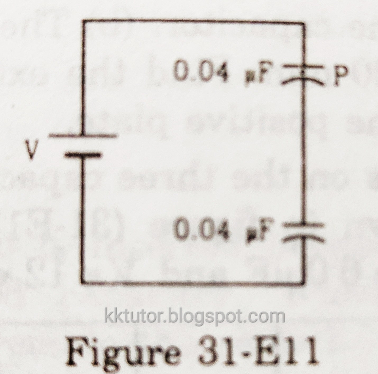
Answer: Mass of the particle,
m = 10 mg =1.0x10⁻⁵ kg.
The charge on the particle
Q =-0.01 µC =-0.01x10⁻⁶ =-1.0x10⁻⁸ C.
The weight of the particle acts downward. The direction of the electric field is also downward between the capacitors, but the charge on the particle is negative, hence the electric force on the particle is upward. When these two forces are equal and opposite, the particle, P will be in equilibrium. If the electric field between the capacitor plates = E, then the electric force on the particle P = QE.
For equilibrium, QE = mg
→QV'/d =mg,
{V' is P.D. across a capacitor}
→QV'C/εₒA = mg
{Since C =εₒA/d, →d =εₒA/C}
→V' =mgεₒA/QC ----------- (i)
Since both capacitors have the same capacitance, the potential difference across each capacitor will be the same. Hence, V =2V', →V' =V/2. We have the values, C = 0.04 µF =4x10⁻⁸ F, A =100 cm² =0.01 m². Now (i) becomes,
V/2 =1x10⁻⁵*9.8*8.85x10⁻¹²*0.01/(1x10⁻⁸*4x10⁻⁸)
→V =2*21.6x10⁻³ V
=43 mV.
22. Both the capacitors shown in figure (31-E12) are made of square plates of edge a. The separations between the plates of the capacitors are d₁ and d₂, as shown in the figure. A potential difference V is applied between points a and b. An electron is projected between the plates of the upper capacitor along the central line. With what minimum speed should the electrons be projected so that it does not collide with any plate? Consider only the electric forces. 
The figure for Q-22

Answer: The area of plates, A =a². The capacitance of the upper plate,
C' = εₒA/d₁
The capacitance of the lower plate,
C" =εₒA/d₂
The equivalent capacitance, C, of these two capacitors connected in series
1/C = 1/C' +1/C"
→1/C =(d₁+d₂)/εₒA
→C =εₒA/(d₁+d₂)
Charge on the equivalent capacitor,
Q =CV
It will be the charge on each capacitor also. Hence, the potential difference between the upper plate,
V' =Q/C'
=CV/(εₒA/d₁)
={εₒA/(d₁+d₂)}V/(εₒA/d₁)
=d₁V/(d₁+d₂)
Thus, the field inside the upper capacitor,E =V'/d₁ =V/(d₁+d₂)Electric force on the electron F =eE→F =eV/(d₁+d₂) Let the projected velocity of the electron = uSince there is no force on it along the horizontal direction, it will travel horizontally with this uniform velocity, u.Time taken by it to travel the plate length a is t =a/uAt time t, the electron should cover a vertical distance = d₁/2. Since there is an electric force in the vertical direction, it will be an accelerated motion. Acceleration f =F/m→f =eV/{m(d₁+d₂)}From the accelerated motion formula, s =ut+½ft²→d₁/2 =0 +½ft²→t² =d₁/f→(a/u)² =d₁*m(d₁+d₂)/eV→u² =Vea²/{md₁(d₁+d₂)}→u =[Vea²/{md₁(d₁+d₂)}]½
23. The plates of a capacitor are 2.00 cm apart. An electron-proton pair is released somewhere in the gap between the plates, and it is found that the proton reaches the negative plate at the same time as the electron reaches the positive plate. At what distance from the negative plate was the pair released?
Answer: Suppose the pair is at a distance x from the negative plate. So the proton travels a distance x, but the electron travels 2-x cm. The electric force on each of them is F =eE, but opposite in direction. If the mass of an electron is m and that of a proton =m', then the acceleration of the electron f=eE/m, and the acceleration of the proton f' =eE/m'. The initial velocity of each particle is zero. If they both take time t to reach the plates, then from the motion formula,
s =ut+½ft²,
For proton,
x =0 +½(eE/m')t²
→t² =2xm'/eE
For the electron,
2-x =0+½(eE/m)t²
→t² =2m(2-x)/eE
Equating these two values of t², we get,
2xm'/eE =2m(2-x)/eE
→xm' =m(2-x)
→(2-x)/x =m'/m
Now, m'/m is the ratio of the weights of a proton and an electron. Since the mass of a proton is 1836 times more than the mass of an electron,
(2-x)/x =1836
→1836x =2-x
→1837x =2
→x =2/1837 cm =1.08x10⁻³ cm
24. Convince yourself that parts (a), (b), and (c) of the figure (31-E13) are identical. Find the capacitances between points A and B of the assembly. 
The figure for Q-24

Answer: All parts are identical, as in each figure, 1 µF and 3 µF capacitors are in series. Similarly, 2 µF and 6 µF are in series. These two series combinations are in a parallel arrangement between points A and B. Also, the 5 µF capacitor is joined as a bridge between the two series-connected capacitors. Hence, all three are identical.
To find the capacitance of the assembly between A and B, let us first remove the 5 µF capacitor and find the potential difference across it in the circuit. Equivalent capacitance of upper series, C' =3/(1+3) =3/4 µF. If a potential difference of V is applied between A and B, a charge in this equivalent capacitor,
Q' =C'V =3V/4 µC, it will also be the charge on each of the 1 µF and 3 µF capacitors. So potential difference across the 1 µF capacitor V' =Q'/(1 µF)
→V' = 3/4 V
Now the lower series, equivalent capacitance,
C" =2*6/(2+6) =12/8 =3/2 µF.
Charge Q" =C"V =3V/2 µC
The potential difference across a 2 µF capacitor, V" =Q"/(2 µF)
→V" =3V/(2*2) =3/4 V
Since V' = V", the potential differences across A and C, and across A and D are the same. Thus, there is no potential difference across the 5 µF capacitor (between C and D). See diagram (a) below.

Diagram for Q-24

With no potential difference across 5 µF capacitor, it is ineffective. Now the assembly can be seen as two capacitors C' and C" in parallel. Diagram (b). Now the equivalent capacitance of the whole given assembly,
C =C' +C" =3/4 µF +3/2 µF
→C =(3+6)/4 µF = 9/4 µF
→C =2.25 µF.
NOTE: In general, if such a configuration of bridge assembly is there in which the proportion of capacitance of the upper series and lower series is the same, then there is no potential difference across the bridging, as in the 5 µF capacitors. Here, for example,
1 µF: 3 µF = 2 µF: 6 µF
25. Find the potential difference Vₐ-Vᵦ between the points a and b shown in each part of the figure (31-E14). 
The figure for Q-25

Answer: (a) The arrangement of figure (a) can be simplified without any difference as below.
 |
| Simplified Diagram |
Equivalent capacitance between points A and B =4 +(4*2)/(4+2) =4+(4/3) =16/3 µF.
Equivalent capacitance between points A and D (series connected 16/3 µF and 2 µF) =(16/3)*2/(16/3 +2)
=(32/3)/(22/3) µF
=32/22 =16/11 µF.
Now the charge supplied by the battery,
Q =CV =(16/11)*12 µC = 192/11 µF
This charge will be on capacitor C and the equivalent capacitors of C', C" and C*. The potential difference across A and B,
V' =Q/(16/3) =3Q/16
→V' =3*192/(11*16) =36/11 volts
Equivalent capacitance of C" and C*,
Cⁿ =C"C*/(C"+C*) =8/6 µF =4/3 µF
Charge on Cⁿ, q =CⁿV' =(4/3)*(36/11) µC = 48/11 µC.
This same charge will be on C" and C*. Hence, the potential difference across C* between a and B,
=q/C* = (48/11)/4 =12/11 V.
(b) Since the batteries are reverse connected, the net potential difference in the circuit = 24 V - 12 V =12 V
The capacitors are connected in series; their equivalent capacitance, C, is given as
1/C = 1/2+1/4
C =2*4/6=4/3 F
Hence, the charge on the equivalent capacitor,
Q = CV =(4/3)*12 = 16 C
It is a series connection, hence this charge will be there on each capacitor. Now, the potential difference across a 2F capacitor,
V' =Q/C =16/2 =8 v
This capacitor is between points a and b. Since the charge in the circuit will flow anticlockwise, point a is at a lower potential than point b. Hence,
Va - Vb = -8 V
(c) Let us name the capacitors and batteries as follows.

Diagram for (c)

Suppose the positive terminal of battery B supplies charge Q to the left plate of capacitor A. So the charge on the right plate = -Q. From symmetry, the negative terminal of battery B' will supply -Q charge to the right plate of the capacitor B. Hence, the left plate of B will have charge Q. Let the charge on the capacitor C be Q'. Since the right plate of A has a charge -Q, the total charge of plates connected to it (plates of B and C) should be equal to Q. Thus, Q' +Q = Q.
→Q' = 0.
So Vₐ -Vᵦ =Q'/C =0 (zero).
(d) Suppose the potential at a = Vₐ = 0.
Potential at A = Vₐ+6 =6 volts.
Potential at B = Vₐ+12 =12 volts
Potential at C = Vₐ+24 =24 volts

Diagram for Q-25(d)
 |
| Diagram for Q-25(d) |
Let the charge on the capacitor plate near A =Q₁, so the charge on the opposite plate =-Q₁.
Similarly, if the charge on the capacitor plate near B =Q₂, then the charge on the opposite plate =-Q₂. And if the charge on the capacitor plate near point C =Q₃, then the charge on the opposite plate = -Q₃. Since all the opposite plates are connected to each other only, the sum of the charges on them should be zero. Vᵦ
→ -Q₁ -Q₂ -Q₃ =0
→Q₁+Q₂+Q₃ = 0 -------- (i)
The potential difference between A and B is
= Vᵦ-6
So, Vᵦ-6 =Q₁/4
→Q₁ =4Vᵦ -24
Similarly, between points B and b,
Q₂ =2(Vᵦ-12)
=2Vᵦ-24
And between points C and bQ₃ =Vᵦ -24
Putting these values in (i) we get,
4Vᵦ-24 +2Vᵦ-24 +Vᵦ-24 = 0
→7Vᵦ =72
→Vᵦ =72/7 =10.3 volts
Hence,Vₐ -Vᵦ =0 -10.3 =-10.3 V
26. Find the equivalent capacitances of the combinations shown in figure (31-E15) between the indicated points. 
The figure for Q-26

Answer: (a) Let us apply a potential difference of V between the points by a battery. 
Diagram for Q-26(a)

Suppose a charge Q is supplied by the positive terminal and -Q by the negative terminal. Q is distributed as Q' to capacitor 1 µF and Q" to 3 µF capacitor. Similarly, -Q is distributed as Q₁' to 3 µF capacitor and Q₁" to 1 µF capacitor on the right side. Let the potential at points C and D be V' and V" respectively. Between C and D, let the 4 µF capacitor get Q* charge. All opposite plates will have opposite charges. We have,
Q₁' = 3V"
Q₁'' =1*V' =V'
Q* = 4(V"-V')
Q' =1*(V-V'') =V-V"
Q" =3*(V-V') =3(V-V')
Now, at point D, all plates are isolated, and the sum of charges will be zero.
Q₁' +Q*-Q' =0
Q' =Q₁' +Q*
→V-V" =3V"+4(V"-V')
→V-V" =7V"-4V'
→8V"-4V' = V ----------- (i)
Also, at C, the sum of charges is zero
Q₁'' -Q"-Q* =0
Q₁'' =Q"+Q*
→1*V' =3(V-V')+4*(V"-V')
→V' =3V-3V'+4V"-4V' =3V-7V'+4V"
→8V'-4V" =3V -------- (ii)
Solving (i) and (ii) we get,
Multiplying (i) by 2 and adding to (ii),
12V" =2V+3V =5V
→V" =5V/12
From (ii),
8V'-4*5V/12 =3V
→8V' =3V+20V/12 =3V+5V/3
→8V' =14V/3
V'= 7V/12
Let the equivalent capacitance = C. Since Q =Q'+Q"
CV =1*(V-V") +3*(V-V')
→CV=V-V"+3V-3V' =4V-5V/12-3*7V/12
→CV =4V-5V/12-7V/4
→C = 4-5/12 -7/4
→C =(48-5-21)/12
→C =22/12 = 11/6 µF.
(b) Let us draw the diagram as below.
 |
| Diagram for Q-26(b) |
We have applied a potential difference of V between points P and N. N is connected to the negative terminal of a battery, and we assume it to be at zero potential. P is connected to the positive terminal of the battery and its potential is at V. We assume the potentials of the points A, B and C as V₁, V₂ and V₃, and the charge on 4 µF capacitors as Q₄ and Q₅.
Now,
Q₁' =3V₁, Q₂' =2V₂, Q₃' =V₃
Q₁ =V-V₁, Q₂=2(V-V₂), Q₃=3(V-V₃)
Q₄ =4(V₁-V₂), Q₅=4(V₂-V₃)
Now, at point A, connected plates will have a total charge of zero. So, Q₁=Q₁'+Q₄
→V-V₁=3V₁+4(V₁-V₂)
→V =8V₁-4V₂ ----- (i)
At point B, the total charge is zero
Q₂ +Q₄=Q₅+Q₂'
→2(V-V₂) +4(V₁-V₂) =4(V₂-V₃)+2V₂
→2V-2V₂ +4V₁-4V₂=4V₂-4V₃+2V₂
→2V =-4V₁+12V₂-4V₃
→V =-2V₁+6V₂-2V₃ ----------(ii)
At point C also,
Q₃' =Q₃+Q₅
→V₃ =3(V-V₃)+4(V₂-V₃)
→V₃ =3V-3V₃+4V₂-4V₃
→3V = 8V₃-4V₂ ---------------(iii)
From (i) 4V₂ =8V₁-V, →V₂ =2V₁-V/4.
From (iii)8V₃=3V+4V₂ =3V+8V₁-V
=2V+8V₁
→V₃ =V₁+ V/4
Putting the value of V₂ and V₃ in (ii), we get,
V =-2V₁+12V₁-3V/2-2V₁-V/2
→V+2V =8V₁
→V₁ =3V/8
V₂ =2(3V/8)-V/4
=3V/4 -V/4
=V/2
And V₃ =3V/8+ V/4
=(3+2)V/8
=5V/8
Since -Q =-Q₁' -Q₂' -Q₃' we have
CV = 3V₁+2V₂+V₃
{Where C is the equivalent capacitance of the whole arrangement between points P and N.}
→CV=3*3V/8+2*V/2+ 5V/8
→C =9V/8 +V +5V/8 µF
→C =(9+ 8+ 5)/8 µF
→C =22/8 = 11/4 µF
(c) Let us connect the indicated points to a battery that applies a potential difference of V between points P and N.

Diagram for Q-26(c)

Through point P a charge Q is supplied by the battery, and through point N, a charge of -Q. N is at zero potential, and P is at V potential. Suppose Q is distributed to the three connected capacitors as Q', Q", and Q*. Similarly, -Q is distributed as -q, -q', and -Q*. Let the charge on the 5 µF capacitor =q", and the potentials of points A and B are V' and V", respectively.
We have, q =4V', q' =8V", Q* =4V
Q' =2(V-V'), Q" =4(V-V"), q" =5(V'-V")
Capacitors connected to A have isolated plates. Hence, the sum of charges on these plates will be zero.
-Q' + q +q" =0
→-2(V-V') + 4V' +5(V'-V") =0
→-2V+2V' +4V'+5V'-5V" =0
→-2V +11V' -5V"=0
→11V'-5V" = 2V ---- (i)
Similarly, point B is isolated
-Q" -q" +q' =0
→ -4(V-V")-5(V'-V")+8V" =0
→ -4V+4V" -5V'+5V"+8V" =0
→ 17V"-5V' =4V ------ (ii)
Multiplying (i) by 17/5 and adding to (ii),11*17V'/5 -5V' =2*17V/5+4V→(11*17-25)V'/5 = (34+20)V/5→ 162 V' =54V → V' = V/3Putting this value in (ii),17V"-5V/3 =4V→17V" =17V/3 →V" =V/3
Point N is also connected to isolated capacitor plates. Hence, the supplied -Q charge is distributed to these plates.-q -q' -Q* =-Q→4V' +8V" +4V = CV{Where C is the equivalent capacitance of the arrangement between P and N.}→CV =4V/3 +8V/3 +4V→ C =4/3 +8/3 +4 =(4 +8 +12)/3 =24/3 =8 µC
(d) Let us apply a potential difference of V volts across the given points P and N. N is connected to the negative terminal of a battery, and we assume its potential at zero. The potential of point P is V. If P receives a charge Q⁰ then N receives a charge of -Q⁰. 
Diagram for Q- 26(d)
Q⁰ is distributed to connected capacitors 2 µF and 4 µF as Q and Q' respectively, considering symmetry as shown in the figure. Similarly, -Q⁰ is distributed to 4 µF and 8 µF capacitors as -q and -q" respectively. We take the potential of A and D = V' and the potential of B and C =V". Charges on capacitors between these points are Q" and Q* as shown in the diagram, considering symmetry.Now, q =4V', q' =8V", Q =2(V-V'), Q' =4(V-V"), Q" =6(V"-V'), Q* =6(V"-V") =0
Sum of charges on plates connected to point A =0.→q+Q"-Q =0→4V' +6(V"-V') -2(V-V') =0→4V' +6V" -6V' -2V+2V' =0→6V" =2V→V" =V/3
Similarly, at point B,q'+Q*-Q'-Q" =0→8V"+0 -4(V-V") -6(V"-V') =0→8V" -4V+4V" -6V" +6V' =0→6V" +6V' =4V→6V/3 +6V' =4V→6V' = 2V →V' =V/3.
Considering the distribution of charge -Q⁰,-Q⁰ =-2q -2q'→CₑV =2*4V' +2*8V"Where Cₑ is the equivalent capacitance between the given points.→CₑV =8*V/3 +16*V/3→Cₑ =24/3 =8 µF.
 |
| Diagram for Q- 26(d) |
27. Find the capacitances of the combination shown in figure (31-E16) between A and B. 
The figure for Q-27

Answer: Let us draw and name some points in the diagram below.

Diagram for Q-27

In the path GMH, two capacitors are in series. The equivalent capacitance of these two, C', is given as
1/C' = 1/2 +1/2 =1
→C' =1 µF.
Now this C' is in parallel with 1 µF capacitor between G and H. The equivalent capacitance of these two capacitors,
C" = C' +1 = 1 +1 =2 µF.
Now this C" and 2 µF between points G and E are in series. The equivalent capacitance of these two,
1/C* = 1/C" +1/2 =1/2 +1/2 = 1 →C* = 1 µF
Between points E and F, C* and 1 µF are in parallel {See diagram (b)}. The equivalent capacitance of these two
C₁ =C* +1 =1 +1 =2 µF.
C₁ between E and F, and 2 µF between E and C are in series. The equivalent capacitance of these two is given as
1/C₂ =1/C₁ +1/2 =1/2 +1/2 =1
→C₂ = 1 µF.
Now, 1 µF capacitor between points C and D, and C₂ is in parallel. The equivalent capacitance of these two
C₃ =C₂ +1 = 1 +1 =2 µF
Between points A and B, C₃ and 2 µF are in series {Diagram (c)}. The equivalent capacitance between A and B is given
1/Cₑ =1/C₃ +1/2 =1/2 +1/2 =1
→Cₑ = 1 µF.
28. Find the equivalent capacitances of the infinite ladder shown between points A and B. 
The figure for Q-28

Answer: Suppose the capacitance between points A and B = C. Since the series is infinite, the capacitance between points D and E on the right is also =C. Now the series becomes as in diagram (b).
Diagram for Q-28

In the path ADEB, 2 µF and C are in series. The equivalent capacitance of these two is given as,
1/C' =1/2 +1/C = (C+2)/2C
→C' =2C/(C+2)
Now C' and 1 µF are in parallel. The equivalent capacitance of these two is the equivalent capacitance of the whole arrangement between A and B, which we have assumed as C. Hence,
C =C' +1 =2C/(C+2) +1
→C =(2C +C+2)/(C+2)
→C = (3C+2)/(C+ 2)
→ C²+2C =3C +2
→C² -C -2 =0
→C² -2C +C -2 =0
→C(C-2) +(C-2) =0
→(C-2)(C+1) =0
Either C = 2 µF or -1 µF.
Since negative capacitance is not acceptable, C =2 µF.
29. A finite ladder is constructed by connecting several sections of 2 µF, 4 µF capacitor combinations as shown in figure (31-E18). It is terminated by a capacitor of capacitance C, such that the equivalent capacitance of the ladder between the points A and B becomes independent of the number of sections in between? 
The figure for Q-29

Answer: The given condition will be fulfilled if the equivalent capacitance of the end section becomes equal to C. Let us calculate the capacitance of the rightmost end section.
C and 4 µF are in series. The equivalent capacitance of these two is given as,
1/C' =1/C +1/4 =(C+4)/4C
→C' =4C/(C+4)
Now C' and 2 µF are in parallel, we have to make the equivalent capacitance of these two as C. So
C' +2 =C
→4C/(C+4) +2 = C
→4C+2C+8 =C² +4C
→C²-2C-8 = 0
→C² -4C +2C -8 =0
→C(C-4) +2(C-4) =0
→(C-4)(C+2) =0
→Either C =4 µF or -2 µF. We will take the positive value, hence, C =4 µF.
30. A charge of +2.0x10⁻⁸ C is placed on the positive plate and a charge of -1.0x10⁻⁸ C on the negative plate of a parallel plate capacitor of capacitance 1.2x10⁻³ µF. Calculate the potential difference developed between the plates.
Answer: When a simple parallel plate capacitor has equal and opposite charges on its plates (Q and -Q), we say the charge on the capacitor is Q. This Q is the net average charge, i.e., {Q-(-Q)}/2. When there are unequal charges, the net average charge on the capacitor,
q ={Q-(-Q')}/2,
here, q ={2x10⁻⁸ -(-1.0x10⁻⁸)}/2
→q =3x10⁻⁸/2 =1.5x10⁻⁸ C.
Given capacitance C' =1.2x10⁻³ µF
→C' =1.2x10⁻⁹ F
Hence, the potential difference developed between the plates,
V =q/C'
=1.5x10⁻⁸/1.2x10⁻⁹ V
=15/1.2 V
=12.5 V
31. A charge of 20 µC is placed on the positive plate of an isolated parallel-plate capacitor of capacitance 10 µF. Calculate the potential difference developed between the plates.
Answer: Since the capacitors are isolated, the charge of 20 µC given to one of the plates will get distributed to each of the faces of this plate. So the inner face of this plate has 10 µC charge. The charge on the other plate is zero, but the 10 µC charge on the first plate induces -10 µC charge on the inner surface of the other plate. To keep the total charge zero on this plate, the outer surface gets a charge of 10 µC. So the inner surfaces of the plates have 10 µC and -10 µC of charge. Thus, the charge on the effective capacitor is q =10 µC.
If we understand the above process, the charge on the capacitor can be directly calculated as q =(20-0)/2 =10 µC.
Given capacitance C = 10 µF.
The potential difference developed between the plates, V = q/C
→V = (10 µC)/(10 µF) = 1 volt.
32. A charge of 1 µC is given to one plate of a parallel plate capacitor of capacitance 0.1 µF, and a charge of 2 µC is given to the other plate. Find the potential difference developed between the plates.
Answer: Given that the charge on one plate q'=1 µC and the charge on the other plate q" =2 µC.
As discussed in the previous problem, the effective charge on the capacitor can be directly calculated as,
q =(q"-q')/2 =(2-1)/2 µC =0.5 µC.
Hence, the potential difference developed between the plates,
V =q/C =(0.5 µV)/(0.1 µF) =5 volts
33. Each of the plates shown in figure (31-E19) has a surface area (96/εₒ)x10⁻¹² F-m on one side and the separation between the consecutive plates is 4.0 mm. The emf of the battery connected to is 10 volts. Find the magnitude of the charge supplied by the battery to each of the plates connected to it. 
The figure for Q-33

Answer: Area of each surface, A =(96/εₒ)x10⁻¹² F-m. Separation between the plates, d =4.0 mm =0.004 m. Four plates in the figure make three capacitors. The capacitance of each of the capacitors, C =εₒA/d
→C =εₒ*(96/εₒ)x10⁻¹²/0.004 F
→C =24x10⁻⁻⁹ F =2.4x10⁻⁸ F
Since each plate is not connected to the battery terminal, it is not a parallel combination. The second and fourth plates are isolated, hence it is a series combination. So the equivalent capacitance C' is given as
1/C' =1/C +1/C +1/C = 3/C
→C' =C/3 =2.4x10⁻⁸/3 F =0.8x10⁻⁸ F
→C' =8x10⁻⁹ F
Potential difference, V =10 volts
Hence the charge on the equivalent capacitor,
Q = CV =8x10⁻⁹*10 =8x10⁻⁸ C

Diagram for Q-33

In the series connection, the charge on the equivalent capacitor =the charge on the individual capacitor.
Hence, the charge on each capacitor, also Q =8x10⁻⁸ C
From the figure, the charge on each connected plate (1st and 3rd plate) =2Q =2*8x10⁻⁸ C =0.16x10⁻⁶ C =0.16 µC.
34. The capacitance between the adjacent plates shown in figure (31-E20) is 50 nF. A charge of 1.0 µC is placed on the middle plate. (a) What will be the charge on the outer surface of the upper plate? (b) Find the potential difference developed between the upper and the middle plates. 
The figure for Q-34

Answer: (a) The capacitance between the upper and middle plate, C =50 nF.
Charge on the upper plate = zero,
Charge on the middle plate =1.0 µC,
Hence, the charge on the capacitor comprising the upper two plates,
Q =(1 µC -0)/2 =0.50 µC,
It means, the charge on the upper surface of the middle plate =0.50 µC and the charge on the lower surface of the upper plate = -0.50 µC,
Since the total charge on the upper plate is zero, the charge on the outer surface of the upper plate must be opposite of -0.50 µC, i.e., 0.50 µC,
(b) The potential difference developed between the upper and middle plates,
V =Q/C =(0.50 µC)/(50 nF)
=(0.50x10⁻⁶ C)/(50x10⁻⁹ F)
=0.01x10³ V
=10 V.
35. Consider the situation of the previous problem. If 1.0 µC is placed on the upper plate instead of the middle, what will be the potential difference between (a) the upper and the middle plates and (b) the middle and the lower plates?
Answer: (a) Same as in the solution of the previous problem, the charge on the capacitor of the upper two plates,
Q =(1-0)/2 =0.50 µC
Hence, the potential difference developed between the upper two plates,
V =Q/C =(0.50 µC)/(50 nF) =10 V.

Diagram for Q-35
(b) The charge distribution on plate surfaces is shown in the diagram above. Opposite surfaces will develop opposite charges. Since the middle and the lower plates have total charges equal to zero, both sides of these plates will also have equal and opposite charges.

As we see, the charge on the capacitor of the lower two plates is also equal to Q =0.50 µC. Hence, the potential difference developed between the middle and lower plates, V =Q/C
→V =(0.50 µC)/(50 nF) =10 V.
36. Two capacitors of capacitances 20.0 pF and 50 pF are connected in series with a 6.00 V battery. Find (a) the potential difference across each capacitor and (b) the energy stored in each capacitor.
Answer: Given C' =20.0 pF, C" =50 pF
V =6.00 V,
Equivalent capacitance in series, C is given as
1/C =1/C' +1/C"
→1/C =1/20 +1/50 = (5+2)/100
→C =100/7 pF.
The charge on the equivalent capacitor,
Q = CV = (100/7)*6 = 600/7 pC.
(a) Since the charge on each capacitor in a series combination is the same as on the equivalent capacitor, the charge on each of the capacitors is
Q = 600/7 pC.
So, the potential difference across a 20 pF capacitor, V' =Q/C'
=(600/7 pC)/(20 pF)
=30/7 Volt
=4.29 V,
The potential difference across a 50 pF capacitor, V" =Q/C"
=(600/7 pC)/(50 pF)
=1.71 V
(b) The energy stored in a capacitor is given as,
E =½QV
So, energy stored in a 20 pF capacitor,
E' =½*(600/7 pC)*4.29 pJ
=184 pJ
And the energy stored in a 50 pF capacitor,
E" =½(600/7 pC)*1.71 pJ
=73.3 pJ
37. Two capacitors of capacitances 4.0 µF and 6.0 µF are connected in series with a battery of 20 V. Find the energy supplied by the battery.
Answer: Given, C' =4.0 µF, C" =6.0 µF, V =20 volts.
C' and C" are connected in series. Equivalent capacitance C is given as,
1/C =1/C' +1/C",
→C =C'C"/(C'+C")
=4*6/(4+6)
=24/10 µF
=2.4 µF
Hence, the charge on the equivalent capacitor,
Q =CV =2.4*20 µC =48 µC
In supplying this charge, the battery has to do work. It moves the charge Q through 20 V. Hence, the energy supplied by the battery is equal to the work done, which is =QV
=(48 µC)*(20 volts)
=960 µJ.
{Please note that the energy supplied by the battery (QV) is double the energy stored on the capacitor (½QV). You may wonder where the half energy goes. The answer is that half the energy supplied by the battery is used to heat the wires or other appliances}
38. Each capacitor in figure (31-E21) has a capacitance of 10 µF. The emf of the battery is 100 V. Find the energy stored in each of the four capacitors.

The figure for Q-38

Answer: Capacitors b and c are connected in parallel, so the equivalent capacitance of b and c is given as,
C* =10 +10 =20 µF.
C* is connected in series with two other capacitors, each of 10 µF. Hence, the equivalent capacitance of the whole arrangement C is given as
1/C =1/10 +1/20 +1/10
→1/C =5/20 =1/4
→C =4 µF
Potential difference =100 V,
Hence, the charge on the equivalent capacitor Q =CV =4*100 =400 µC.
This charge Q will be on each of the series-connected capacitors, i.e., 10 µF, C* and 10 µF.
Energy stored on each of 10 µF capacitors, i.e., a and d =Q²/2C =(400)²/(2*10) µJ
=8000 µJ =8 mJ.
Now the charge Q =400 µC on the capacitor C* will be equally divided among each of the 10 µF capacitors connected in parallel, i.e., Q' =200 µC. Hence, the energy stored in capacitors b and c =Q'²/2C
=(200)²/(2*10) µJ
=2000 µJ
=2 mJ.
39. A capacitor with stored energy of 4.0 J is connected with an identical capacitor with no electric field in between. Find the total energy stored in the two capacitors.
Answer: Stored energy of the first capacitor U =Q²/2C =4.0 J.
The capacitance of both capacitors is the same, hence the charge is equally distributed between them. Charge on each capacitor =Q/2.
So the energy stored on each of them =(Q/2)²/2C
=Q²/8C
The total energy stored in the two capacitors =2*Q²/8C
=Q²/4C
=½*Q²/2C
=½*4 J
=2 J.
40. A capacitor of capacitance 2.0 µF is charged to a potential difference of 12 V. It is then connected to an uncharged capacitor of capacitance 4.0 µF as shown in figure (31-E22). Find (a) the charge on each of the two capacitors after the connection. (b) the electrostatic energy stored in each of the two capacitors and (c) the heat produced during the charge transfer from one capacitor to the other. 
The figure for Q-40

Answer: (a) Charge on the 2µF capacitor before connection,
Q =(2 µF)*(12 V) = 24 µC
When it is connected to the 4 µF capacitors as in the given figure, the potential difference across the plates of each capacitor is the same, say =V'.
If Q' and Q" are charges on 2 µF and 4 µF capacitors, respectively, then,
V' =Q'/2, also V' =Q"/4
So, Q'/2 =Q"/4
→Q" =2Q'
But Q' +Q" = Q
→Q' +2Q' =24 µC
→3Q' =24 µC
→Q' = 8 µC
So the charge on the 2 µF capacitor is 8 µC, and on the 4 µF capacitor =2*8 =16 µC.
(b) Electrostatic energy stored in 2 µF capacitor =Q'²/(2*2) =8²/4 =16 µJ.
{Since U =Q²/2C}
Energy stored in a 4 µF capacitor
=Q"²/(2*4) =16²/8 µJ
=32 µJ
(c) Energy stored in 2 µF capacitor before connection =Q²/2C
=24²/(2*2)
=144 µJ
Energy stored in two capacitors after connection =16 µJ +32 µJ =48 µJ
The heat produced during the charge transfer =144 µJ -48 µJ
=96 µJ.
41. A point charge Q is placed at the origin. Find the electrostatic energy stored outside the sphere of radius R centered at the origin.
Answer: The sphere will have a charge Q appearing on the outer surface. The capacitance of a spherical capacitor is given as,
C =4πεₒR.
Hence, the energy stored in this capacitor U = Q²/2C
= Q²/8πεₒR.
42. A metal sphere of radius R is charged to a potential V. (a) Find the electrostatic energy stored in the electric field within a concentric sphere of radius 2R. (b) Show that the electrostatic field energy stored outside the sphere of radius 2R equals that stored within it.
Answer: As we saw in the previous problem, the electrostatic energy stored outside a spherical capacitor of radius R is,
U =Q²/(8πεₒR),
Hence, the electrostatic energy stored outside a spherical capacitor of radius 2R is,
U' =Q²/(8πεₒ*2R) =Q²/(16πεₒR)
(a) Hence, the electrostatic energy stored in the electric field within a concentric sphere of radius 2R =U -U'
=Q²/(8πεₒR) -Q²/(16πεₒR)
=Q²/(16πεₒR)
=(CV)²/(16πεₒR)
{Put the value of C}
=(4πεₒRV)²/(16πεₒR)
=(16π²εₒ²R²V²)/(16πεₒR)
=πεₒRV².
(b) Electrostatic field energy stored outside the sphere of radius 2R is
U' = Q²/(16πεₒR) ---- (i)
Electrostatic field energy stored inside this sphere is the same as the energy stored between the sphere of radius R and the sphere of radius 2R because the field inside the smaller sphere is zero. This energy has been derived in the above solution (a) as
U -U' =Q²/(8πεₒR) -Q²/(16πεₒR)
=Q²/(16πεₒR) ------- (ii)
Comparing (i) and (ii), both are equal.
43. A large conducting plane has a surface charge density of 1.0x10⁻⁴ C/m². Find the electrostatic energy stored in a cubical volume of edge 1.0 cm in front of the plane.
Answer: Given σ =1.0x10⁻⁴ C/m².
The electric field in front of the large conducting plane,
E = σ/εₒ
Energy per unit volume in a space having field E is,
u =½εₒE²
Cubical volume = a³, where a is the edge of the cube. Hence, the energy stored in the cubical volume,
U =½εₒE²a³
=½εₒ(σ/εₒ)²a³
=½σ²a³/εₒ
Putting the respective values we get,
U=½*(1.0x10⁻⁴)²*(0.01)³/8.85x10⁻¹² J
=5.6x10⁻⁴ J.
44. A parallel-plate capacitor having a plate area of 20 cm² and a separation between the plates of 1.00 mm is connected to a battery of 12.0 V. The plates are pulled apart to increase the separation to 2.0 mm. (a) Calculate the charge flown through the circuit during the process. (b) How much energy is absorbed by the battery during the process? (c) Calculate the stored energy in the electric field before and after the process. (d) Using the expression for the force between the plates, find the work done by the person pulling the plates apart. (e) Show and justify that no heat is produced during this transfer of charge as the separation is increased.
Answer: Given, A =20 cm² =0.002 m².
d = 1 mm =0.001 m, V =12.0 volt, hence the capacitance,
C =εₒA/d =εₒ*0.002/0.001
=2εₒ
Charge on this capacitor, Q =CV
→Q =2εₒ*12 =24εₒ
When the distance is increased to 2 mm, the capacitance is now
C' = εₒ*0.002/0.002 =εₒ
Charge on this capacitor, Q' =C'V
→Q' =εₒ*12 =12εₒ
(a) Hence, the charge flown through the circuit during the process is
Q-Q' = 24εₒ -12εₒ =12εₒ
=12*8.85x10⁻¹² F
=1.06x10⁻¹⁰ C.
(b) The energy absorbed by the battery during the process
=(Q-Q')V
=12εₒV
=12*8.85x10⁻¹²*12 J
=12.7x10⁻¹⁰ J
(c) Stored energy in the electric field before the process
U =½QV
=½*24εₒ*12
=144εₒ
=144*8.85x10⁻¹² J
=12.7x10⁻¹⁰ J
Stored energy in the electric field after the process,
U' =½Q'V
=½*12εₒ*12
=64εₒ
=64*8.85x10⁻¹² J
=6.37x10⁻¹⁰ J.
(d) Since the capacitor is connected to the battery, the charge on it varies during the pulling process. The charge on the capacitor Q =CV =εₒAV/x, where x is the distance between the plates.
The electric field due to the positive plate, E =σ/2εₒ =Q/2Aεₒ
The force on the negative plate having charge = -Q will be
F =(-Q)E =-QE
The person will do work against this force in pulling the plates apart. He will have to pull it slowly, and the force by him will be =QE.
Work done by him in pulling the plate by a small distance dx,
dU =QEdx =Q*(Q/2Aεₒ)dx
→dU =(Q²/2Aεₒ)dx
→dU ={(εₒAV/x)²/2Aεₒ}dx
→dU =[{(εₒAV²)/2}/x²]dx
Hence U =(εₒAV²/2)∫(1/x²)dx
=(εₒAV²/2)*[-1/x]
Applying lower limit x =1 mm =0.001 m, upper limit, x =2 mm =0.002 m, we get
U =(εₒAV²/2)*[-1/0.002 +1/0.001]
=½εₒAV²*500
=250*8.85x10⁻¹²*0.002*12² J
=6.37x10⁻¹⁰ J.
(e) The energy absorbed by the battery is equal to the sum of the loss of the stored energy during the process and the work done by the person. Hence, no heat is produced during the process.
45. A capacitor having a capacitance of 100 µF is charged to a potential difference of 24 V. The charging battery is disconnected and the capacitor is connected to another battery of emf 12 V with the positive plate of the capacitor joined with the positive terminal of the battery. (a) Find the charge on the capacitor before and after the reconnection. (b) Find the charge flown through the 12 V battery. (c) Is work done by the battery or is it done on the battery? Find its magnitude. (d) Find the decrease in the electrostatic field energy. (e) Find the heat developed during the flow of charge after reconnection.
Answer: (a) Given C =100 µF. Before reconnection, V =24 volts. Hence, the charge on the capacitor,
Q =CV =100*24 µC =2400 µC.
After reconnection, V =12 volts. Hence, the charge now is
Q' =100*12 µC =1200 µC.
(b) The charge flown through the 12 V battery = Q -Q' =2400 -1200 µC
=1200 µC.
(c) Since the charge of 1200 µC flows against the emf of 12 V battery, the work is done on the battery. Its magnitude =(Q -Q')V
=1200*12 µJ
=14400 µJ
=14.4 mJ.
(d) The decrease in electrostatic field energy =U -U'
=½QV -½Q'V'
=½*2400*24 -½*1200*12 µJ
=28800 -7200 µJ
=21600 µJ
=21.6 mJ.
(e) The loss of electrostatic field energy =21.6 mJ but the work done on the battery =14.4 mJ. Hence, the heat developed during the flow of charge after reconnection =21.6 -14.4 mJ =7.2 mJ.
46. Consider the situation shown in figure (31-E23). The switch S is open for a long time and then closed. (a) Find the charge flown through the battery when the switch S is closed. (b) Find the work done by the battery. (c) Find the change in energy stored in the capacitors. (d) Find the heat developed in the system.
The figure for Q-46

Answer: (a) Since the switch is open for a long time, both capacitors are in series. Equivalent capacitance C' is
1/C' =1/C +1/C =2/C
→C' =C/2
The charge on the equivalent capacitor
Q =C'Ɛ =CƐ/2
When the switch S is closed, the plates of the capacitor on the right side have both come to the same potential, and the earlier charges on its plate nullify each other. Now, only one capacitor on the left is effective. Charge on this capacitor,
Q' =CƐ.
Hence, the charge flew through the battery when switch S is closed =Q'-Q
=CƐ -CƐ/2 =CƐ/2.
(b) The work done by the battery
=Charge flown*emf
=(Q'-Q)*Ɛ =CƐ/2*Ɛ
=CƐ²/2.
(c) Energy stored initially U =½QV
=½*(CƐ/2)*Ɛ =CƐ²/4
Energy stored after the switch S is closed, U' =½Q'Ɛ =½CƐ*Ɛ =½CƐ²
Hence, the change in energy stored in capacitors =U' -U
=½CƐ² -CƐ²/4
=CƐ²/4.
(d) The work done by the battery {from (b)} =CƐ²/2
The change in energy stored in capacitors {from (c)} =CƐ²/4
The difference is the loss of energy, which is used to develop heat in the system. It is equal to,
CƐ²/2 -CƐ²/4 =CƐ²/4.
47. A capacitor of capacitance 5.00 µF is charged to 24 V and another capacitor of capacitance 6.0 µF is charged to 12.0 V. (a) Find the energy stored in each capacitor. (b) The positive plate of the first capacitor is now connected to the negative plate of the second and vice versa. Find the new charges on the capacitor. (c) Find the loss of electrostatic energy during the process. (d) Where does this energy go?
Answer: (a) C =5 µF, V = 24 volts,
Energy stored, E =½CV²
→E =½*5*24² =1440 µJ =1.44 mJ.
For the other capacitor, C' =6 µF, V' =12 volts,
hence the energy stored, E' =½C'V'²
→E' =½*6*12² =432 µJ =0.432 mJ.
(b) The charge Q on the first capacitor,
Q =CV =5*24 =120 µC
Charge on the second capacitor,
Q' =C'V' =6*12 =72 µC
When the 120 µC plate of the first capacitor is connected to the -72 µC plate of the other, the net total charge on both the connected plates is Q" =120-72 =48 µC. Similarly, the net total charge on another pair of connected plates =-120 +72 =-48 µC.
 |
| Diagram for the Q-47 |
Let V" be the potential difference across the plates. Then,
Q" =C"V"
We can see that the plates are connected in parallel. Hence,
C" =C +C' = 5+6 =11 µF.
V" =Q"/C" =48/11 volts
Now the charge on the first capacitor
q =CV" =5*48/11 =21.8 µC.
The charge on the second capacitor,
q' =C'*V" =6*48/11 =26.2 µC.
(c) The electrostatic energy before connection {from (a)},
U =E+E' =1.44+0.432 mJ =1.872 mJ
The electrostatic energy after connection,
U' =½C"V"² =½*11*(48/11)² µJ
=104.73 µJ
=0.105 mJ
Hence, the loss of electrostatic energy during the process =U -U'
=1.872 -0.105 mJ
≈1.77 mJ.
(d) This lost energy is dissipated as heat.
48. A 5.0 µF capacitor is charged to 12 V. The positive plate of this capacitor is now connected to the negative terminal of a 12 V battery and vice versa. Calculate the heat developed in the connecting wires.
Answer: C = 5 µF, V =12 volts. The charge on the capacitor, Q =CV
→Q =5*12 =60 µC.
So the charge on the positive plate of the capacitor is 60 µC and on the negative plate -60 µC.
When the plates of this capacitor are connected to a 12 V battery with reverse polarity, the negative plate becomes positive and the positive plate becomes negative. Since the potential difference is still 12 V, the charge on the capacitor is 60 µC. Consider the initial negative plate with charge -Q. After connection to the battery, this plate has now charge Q. Hence, the charge supplied by the battery after connection =Q-(-Q) =2Q. Hence, the energy supplied by the battery U =(2Q)V,
→U =2*60*12 µJ =1440 µJ.
Since the charge on the capacitor and the potential difference across it remain the same before and after the connection with the battery, the energy stored in it remains the same. Hence, the total energy supplied by the battery is used in heating the wires. So the heat developed in the connecting wires =1440 µJ =1.44 mJ.
49. The two square faces of a rectangular dielectric slab (dielectric constant 4.0) of dimensions 20 cm x 20 cm x 1.0 mm are metal-coated. Find the capacitance between the coated surfaces.
Answer: Dielectric constant of the slab, K = 4.0, A =20 cm x 20 cm =400 cm² =0.04 m², d =1.0 mm =0.001 m.
The capacitance between the coated surfaces, C =KεₒA/d
→C =4.0*8.85x10⁻¹²*0.04/0.001 F
→C =1.42x10⁻⁹ F =1.42 nF.
50. If the above capacitor is connected across a 6.00 V battery, find (a) the charge supplied by the battery, (b) the induced charge on the dielectric and (c) the net charge appearing on one of the coated surfaces.
Answer: The potential difference across this capacitor =6.00 V, C =1.42 nF.
(a) The charge supplied by the battery,
Q =CV =1.42x6.00 nC =8.52 nC.
(b) The induced charge on the dielectric,
Qp =Q(1 -1/K)
=8.52*(1-1/4) nC
=8.52*3/4 nC
=6.4 nC.
(c) The net charge appearing on one of the coated surfaces =Q -Qp
=8.5 -6.4 =2.1 nC.
51. The separation between the plates of a parallel-plate capacitor is 0.500 cm and its plate area is 100 cm². A 0.400 cm thick metal plate is inserted into the gap with its faces parallel to the plates. Show that the capacitance of the assembly is independent of the position of the metal plate within the gap and find its value.
Answer: When the metal plate is inserted into the parallel plate capacitor, both of its parallel surfaces get induced charges. Two gaps on either side make two capacitors joined by the metal in series.
Diagram for Q-51

Let the gap on one side = x, plate thickness = t, and separation of the given capacitor =d. So the gap on the other side =d-t-x.
The capacitance of the capacitor having a gap =x,
C' =εₒA/x, where A is the plate area.
The capacitance of the capacitor having a gap d-t-x,
C" =εₒA/(d-t-x)
Equivalent capacitance C is given as
1/C =1/C' +1/C"
→C =C'C"/(C' +C")
=(εₒA)²/[x(d-t-x)(εₒA){1/x +1/(d-t-x)}]
=εₒA/[x(d-t-x)*(d-t-x+x)/{x(d-t-x)}]
=εₒA/(d-t).
This expression for the capacitance of the assembly is independent of x, i.e., independent of the position of the metal plate within the gap. We can find the value of C by putting the given data.
Given, d =0.500 cm =0.005 m,
t =0.400 cm =0.004 m,
A =100 cm² =0.01 m²
C =εₒA/(d-t)
=8.85x10⁻¹²*(0.01)/(0.005-0.004)
=8.85x10⁻¹²*10 F
=88.5x10⁻¹² F
=88.5 pF.
52. A capacitor stores 50 µC charge when connected across a battery. When the gap between the plates is filled with a dielectric, a charge of 100 µC flows through the battery. Find the dielectric constant of the material inserted.
Answer: Initial charge, Q =50 µC.
When the gap is filled with a dielectric having a dielectric constant K, 100 µC flows through the battery. So now the charge, Q' =50 +100 =150 µC.
Initially, capacitance C =εₒA/d
Finally, capacitance C' =KεₒA/d
Hence C'/C =K
→(Q'/V)/(Q/V) =K, {V=Battery emf}
→Q'/Q =K
→K =Q'/Q =150/50 =3.
53. A parallel plate capacitor of capacitance 5 µF is connected to a battery of emf 6 V. The separation between the plates is 2 mm. (a) Find the charge on the positive plate. (b) Find the electric field between the plates. (c) A dielectric slab of thickness 1 mm and dielectric constant 5 is inserted into the gap to occupy the lower half of it. Find the capacitance of the new combination. (d) How much charge has flown through the battery after the slab is inserted?
Answer: (a) d = 2 mm =0.002 m.
C =5 µF, V = 6 volts. Since Q =CV,
The charge on the capacitor
Q =(5 µF)*(6 V) =30 µC.
It means the charge on the positive plate of the capacitor is +30 µC.
(b) The electric field between the plates,
E = V/d
=(6 V)/(0.002 m)
=3000 V/m
=3x10³ V/m.
(c) Initial Capacitance, C =εₒA/d
→5x10⁻⁶ =εₒA/d
→εₒA =5x10⁻⁶*d -------------(i)
Thickness of dielectric = t = 1 mm =0.001 m
Dielectric constant = K =5
Now the capacitance of the combination
C* =εₒA/{d-t(1-1/K)}
Putting value from (i)
=5x10⁻⁶*d/{d-t(1-1/k)}
=5x10⁻⁶*2/{2-1(1-1/5)}
{Since the numerator and denominator have d and t, we do not have to change the unit}
=5x10⁻⁶*2/(6/5)
=8.33 µF.
(d) The charge flown through the battery after inserting the dielectric =Q' -Q
=C*V -CV
=(C* -C)V
=(8.33 -5)*6
=3.33*6 µC
=20 µC.
54. A parallel plate capacitor has a plate area of 100 cm² and a plate separation of 1.0 cm. A glass plate (dielectric constant 6.0) of thickness 6.0 mm and an ebonite plate (dielectric constant 4.0) are inserted one over the other to fill the space between the plates of the capacitor. Find the new capacitance.
Answer: A = 100 cm² =0.01 m².
The two dielectrics will act as separate capacitors connected in series, the junction of the dielectrics being a common plate for the two.
Separation of the first capacitor, d = 6 mm, Dielectric constant K = 6.0 and separation of the second d' =4.0 mm and K' =4.0,
C =εₒAK/d, and
C' =εₒAK'/d'.
The capacitance of the assembly C" is given as,
1/C" =1/C +1/C'
C" =C'C/(C+C')
Now, C'C =(εₒAK'/d')*(εₒAK/d)
=(εₒA)²K'K/d'd
And C +C' =εₒA{K'/d' +K/d}
=εₒA(K'd +Kd')/d'd
Hence
C" ={(εₒA)²K'K/d'd}/{εₒA(K'd+Kd')/d'd}
=εₒAK'K/(K'd+Kd')
=8.85x10⁻¹²*0.01*6*4/(4*0.006+6*0.004)
=44.25x10⁻¹² F
≈44 pF.
55. A parallel plate capacitor having a plate area 400 cm² and separation between the plates 1.00 mm is connected to the power supply of 100 V. A dielectric slab of thickness 0.5 mm and dielectric constant 5.0 is inserted into the gap. (a) Find the increase in electrostatic energy. (b) If the power supply is now disconnected and the dielectric slab is taken out, find a further increase in energy. (c) Why does the energy increase in inserting the slab as well as in taking it out?
Answer: A =400 cm² =0.04 m², d =1 mm =0.001 m, V =100 volts. K =5.
Capacitance, C =εₒA/d
=8.85x10⁻¹²*0.04/0.001 F
=3.54x10⁻¹⁰ F
Stored electrostatic energy,
U = ½CV²
=½*3.54x10⁻¹⁰*10⁴
=1.77x10⁻⁶ J
=1.77 µJ
After the dielectric slab is inserted, the capacitance
C' =εₒA/{d-t(1-1/K)}
=8.85x10⁻¹²*0.04/(0.001-0.0005*0.8)
=5.90x10⁻¹⁰ F
Stored energy now,
U' =½C'V²
=½*5.9x10⁻¹⁰*10⁴
=2.95x10⁻⁶ J
=2.95 µJ
Increase in stored energy =U'-U
=2.95 -1.77 µJ
=1.18 µJ.
(b) In the final state charge on the capacitor, Q' =C'V
→Q' =5.90x10⁻¹⁰*100 C
=5.90x10⁻⁸ C
When the power supply is disconnected, this charge remains on the capacitor. When the dielectric is also removed, its capacitance goes back to the original capacitance C. Now the energy =Q'²/2C
=(5.90x10⁻⁸)²/(2*3.54x10⁻¹⁰)
=4.92 µJ
Hence, the further increase in the energy =4.92 -2.95 µJ
=1.97 µJ.
(c) When the dielectric slab is inserted, the capacitance increases and the capacitor draws more charge from the battery. Hence, the energy stored increases in this process.
In the second case, the battery is disconnected, and the increased charge remains on the capacitor. But with the withdrawal of the dielectric, the capacitance reduces and reverts to the original one. Hence, in the expression of stored energy, U =Q²/2C, since C <C', U increases.
56. Find the capacitances of the capacitors shown in figure (31-E24). The plate area is A and the separation between the plates is d. Different dielectric slabs in a particular part of the figure are of the same thickness and the entire gap between the plates is filled with the dielectric slabs. 
The figure for Q -56

Answer: (a) In this part, the assembly is equivalent to two capacitors joined in series. Separation for each capacitor =d/2.
For the first, C' =εₒAK₁/(d/2)
=2εₒAK₁/d
For the second , C" =εₒAK₂/(d/2)
=2εₒAK₂/d
Hence, the capacitance of the assembly,
C =C'C"/(C'+C")
=(2Aεₒ/d)²K₁K₂/{(2εₒA/d)(K₁+K₂)}
=2εₒAK₁K₂/{d(K₁+K₂)}.
(b) In the second part, the situation is similar. Just the difference is that as if three capacitors are connected in series and the separation of each capacitor is d/3. Capacitances of them are,
First, C' =εₒAK₁/(d/3)
=3εₒAK₁/d
Similarly, for the second
C" =3εₒAK₂/d
For the third, C‴ =3εₒAK₃/d
The equivalent capacitance C is,
1/C =1/C' +1/C" +1/C‴
=(C'C"+C"C‴+C‴C')/C'C"C‴
→C =C'C"C‴/(C'C"+C"C‴+C‴C')
=(3εₒA/d)³K₁K₂K₃/{(3εₒA/d)²(K₁K₂+K₂K₃+K₃K₁)}
=3εₒAK₁K₂K₃/{d(K₁K₂+K₂K₃+K₃K₁)}
(c) In this part, two capacitors with dielectrics are connected in parallel. The separation of each is d, but the plate area for each of them =A/2.
C' =εₒAK₁/2d
C" =εₒAK₂/2d
In parallel, equivalent capacitance
C =C'+C"
=(εₒA/2d)(K₁+K₂)
=εₒA(K₁+K₂)/2d.
57. A capacitor is formed by two square metal plates of edge a, separated by a distance d. Dielectrics of dielectric constant K₁ and K₂ are filled in the gap as shown in figure (31-E25). Find the capacitance. 
The figure for Q -57

Answer: Since the thickness of the dielectric varies, we will have to take the help of integration. Consider an infinitesimal width dx at a distance x from the left as shown in the diagram. This section has two very small capacitors with plate area =adx, separation of lower capacitor =x.tanß and the separation of upper capacitor =d-x.tanß
Diagram for Q-57

These two small capacitors are connected in series. Suppose the capacitance of the upper one is dC₁ and of the lower one is dC₂. Then,
dC₁ =ε₀(adx)K₁/(d-xtanß)
dC₂ =ε₀(adx)K₂/xtanß
The equivalent capacitance dC is given as,
1/dC =1/dC₁+1/dC₂
→dC =dC₁.dC₂/(dC₁+dC₂)
=(εₒadx)²K₁K₂/{x.tanß(d-x.tanß)}(εₒadx){K₁/(d-xtanß)+K₂/(x.tanß}
=εₒaK₁K₂.dx/{K₁xtanß+K₂(d-xtanß)]
=εₒaK₁K₂.dx/{K₂d+(K₁-K₂)tanß*x]
On integration,
∫dC={εₒaK₁K₂/(K₁-K₂)tanß}*[logₑ{K₂d+(K₁-K₂)tanß*x}]
{The integral of the underlined portion is in the form of 1/(a+bx), and we integrate it from x=0 to x=a}
→C={εₒaK₁K₂/(K₁-K₂)tanß}}{logₑ(K₂d+(K₁-K₂)a.tanß)-logₑ(K₂d)}
→C={εₒaK₁K₂/(K₁-K₂)tanß}{logₑ(K₂d+(K₁-K₂)d)/(K₂d)}
{We replace a.tanß =d}
={(εₒa²K₁K₂)/(K₁-K₂)a.tanß}*logₑ{K₁d/(K₂d)}
{Multiplying numerator and denominator by a}
={(εₒa²K₁K₂)/(K₁-K₂)d}logₑ(K₁/K₂)}
={εₒa²K₁K₂*logₑ(K₁/K₂)}/{(K₁-K₂)d}
This is the value of the given composite capacitor.
58. Figure (31-E26) shows two identical parallel plate capacitors connected to a battery through a switch S. Initially, the switch is closed so that the capacitors are completely charged. The switch is now opened and the free space between the plate of the capacitors is filled with a dielectric with a dielectric constant 3. Find the ratio of the initial total energy stored in the capacitors to the final total energy stored. 
The figure for Q -58

Answer: When the switch is closed, the capacitors are connected in a parallel combination. Equivalent capacitance
C' =2C
The energy stored in the capacitors,
U =½(2C)V² =CV².
When the switch is opened and the free space filled with a dielectric with K=3, the capacitance of the capacitor A =KC =3C. The energy stored in capacitor A,
Uₐ =½(3C)V² =3CV²/2
Since the switch is opened, the charge on it remains the same, i.e., Q=CV, but the capacitance increased to 3C. Hence, the energy stored in it Uᵦ =½Q²/(3C) =½(C²V²)/(3C) =CV²/6Hence, the total energy stored in this case =U' =Uₐ+Uᵦ→U' =3CV²/2 +CV²/6 =10CV²/6 =5CV²/3Hence U/U' = CV²/(5CV²/3) =3/5So, U : U' = 3 : 5.
59. A parallel plate capacitor of plate area A and the plate separation d is charged to a potential difference V and then the battery is disconnected. A slab of dielectric constant K is then inserted between the plates of the capacitor so as to fill the space between the plates. Find the work done on the system in the process of inserting the slab.
Answer: The capacitance of the capacitor, C =ε₀A/d. When charged with battery, Q =CV =εₒAV/d.
Energy stored U =½QV
→U =½εₒAV²/d
When the battery is disconnected, the charge remains the same, i.e. = Q. When the dielectric of K is inserted, capacitance is now C' = εₒAK/d.
Hence, the energy stored now is,
U' =½Q²/C'
=½(εₒAV/d)²/(εₒAK/d)
=½εₒAV²/Kd
Increase in energy stored =U' -U
=½εₒAV²/Kd -½εₒAV²/d
=(½εₒAV²/d)*(1/K-1)
The increase in energy of the system is equal to the work done on the system in the process of inserting the slab. So the work done is,
W =(½εₒAV²/d)*(1/K-1)
=εₒAV²(1/K-1)/2d.
60. A capacitor having a capacitance of 100 µF is charged to a potential difference of 50 V. (a) What is the magnitude of the charge on each plate? (b) The charging battery is disconnected and a dielectric of dielectric constant 2.5 is inserted. Calculate the new potential difference between the plates. (c) What charge would have produced this potential difference in the absence of the dielectric slab? (d) Find the charge induced at the surface of the dielectric slab.
Answer: (a) The capacitance, C =100 µF, V = 50 volts. Hence the charge,
Q = CV =100*50 µC =5000 µC
→Q =5 mC.
So the magnitude of the charge on each plate = 5 mC.
(b) When the battery is disconnected, this charge remains on the capacitor. The new capacitance of the capacitor with a dielectric of K =2.5,
C' =KC =2.5*100 =250 µF.
Q = 5000 µC.
Hence, the new potential difference between the plates,
V' =Q/C'
=5000/250 V
=20 V.
(c) In the absence of the dielectric slab, the capacitance C = 100µF. Potential difference = 20 V. The charge required to produce this potential difference,
Q = CV' = 100*20 = 2000 µC = 2 mC.
(d) The charge induced at the surface of the dielectric slab,
Qₚ =Q{1 -1/K}
[Q =5 mC, and K =2.5]
=5*{1 -1/2.5} mC
=5*1.5/2.5 mC
=5*3/5 mC
=3 mC.
61. A spherical capacitor is made of two conducting spherical shells of radii a and b. The space between the shells is filled with a dielectric constant K up to a radius c, as shown in figure (31-E27). Calculate the capacitance. 
The figure for Q-61

Answer: We can think of it as if two spherical capacitors were connected in series. The capacitance of the inner capacitor,
C' =4πεₒcaK/(c-a)
The capacitance of the outer capacitor,
C" =4πεₒbc/(b-c)
Equivalent capacitance C is given by
C =C"C'/(C'+C")
=[(4πεₒ)²abc²K/{(c-a)(b-c)}]/4πεₒc{Ka/(c-a)+b/(b-c)}
=4πεₒKabc/{Ka(b-c)+b(c-a)}.
62. Consider an assembly of three conducting concentric spherical shells of radii a, b and c as shown in figure (31-E28). Find the capacitance of the assembly between points A and B. 
The figure for Q-62

Answer: It is two spherical capacitors connected in series. The capacitance of the inner capacitor,
C' =4πεₒab/(b-a)
The capacitance of the outer capacitor,
C" =4πεₒbc/(c-b)
The equivalent capacitance,
C =C'C"/(C'+C")
=[(4πεₒ)²ab²c/{(b-a)(c-b)}]/[4πεₒb{a/(b-a)+c/(c-b)]
=4πεₒabc/{a(c-b)+c(b-a)}
=4πεₒabc/(ac-ab+bc-ac)
=4πεₒabc/{b(c-a)}
=4πεₒac/(c-a).
63. Suppose the space between the two inner shells of the previous problem is filled with a dielectric of dielectric constant K. Find the capacitance of the system between A and B.
Answer: It is similar to problem 61. The capacitance of the inner spherical capacitor,
C' =4πεₒKab/(b-a)
The capacitance of the outer spherical capacitor,
C" =4πεₒbc/(c-b)
The equivalent capacitance between A and B is,
C =C'C"/(C'+C")
=[(4πεₒ)²Kab²c/{(b-a)(c-b)}]/[4πεₒb{Ka/(b-a)+c/(c-b)}]
=4πεₒKabc/{Ka(c-b)+c(b-a)}.
64. An air-filled parallel-plate capacitor is to be constructed that can store 12 µC of charge when operated at 1200 V. What can be the minimum plate area of the capacitor? The dielectric strength of air is 3x10⁶ V/m.
Answer: Given, Q =12 µC, V =1200 volts, hence capacitance C =Q/V
= 12/1200 µF
= 0.01 µF
Given also the dielectric strength of air =3x10⁶ V/m. It means it is the minimum field at which the breakdown of the dielectric occurs. Hence, for the minimum plate area (A), we take the electric field between the plates, E = dielectric strength of the air
=3x10⁶ V/m
For a uniform field, E = V/d
→d =V/E
=1200/3x10⁶ m
=4x10⁻⁴ m
Now capacitance C = εₒA/d
→A =Cd/εₒ
=0.01x10⁻⁶*4x10⁻⁴/8.85x10⁻¹² m²
=0.45 m².
65. A parallel plate capacitor with a plate area of 100 cm² and a separation between the plates 1.0 cm is connected across a battery of 24 volts. Find the force of attraction between the plates.
Answer: A = 100 cm² =0.01 m²
d = 1.0 cm = 0.01 m
V = 24 volts
The electric field between the plates
E = 𝜎/2εₒ =Q/2Aεₒ
The force of attraction between the plates,
F =QE =Q²/2Aεₒ
=(CV)²/2Aεₒ
=(εₒAV/d)²/2Aεₒ
=εₒAV²/2d²
=8.85x10⁻¹²*0.01*24²/{2*(0.01)²} N =2.54x10⁻⁷ N.
66. Consider the situation shown in figure (31-E29). The width of each plate is b. The capacitor plates are rigidly clamped in the laboratory and connected to a battery of emf Ԑ. All surfaces are frictionless. Calculate the value of M for which the dielectric slab will stay in equilibrium. 
The figure for Q-66

Answer: Let the length of plates with dielectric = x. Area of plates =bx.
The capacitance of the portion with dielectric, C' =Kεₒbx/d
The capacitance of the portion without dielectric, C" =εₒb(l-x)/d
Since the area of plates in this capacitor =b(l-x)
These two types of capacitors are connected in parallel, hence the equivalent capacitance C = C'+C"
→C =(εₒb/d){Kx+(l-x)}
→C =εₒb{l+x(K-1)}/d ----- (i)
Suppose the resultant of electric forces F pulls the dielectric inside and we consider a very, very small displacement dx along F (as shown in the figure below). Due to this, there will be a very small change in the capacitance, say dC. 
Diagram for Q-66

Differentiating (i) both sides with respect to x,
dC/dx =εₒb(K-1)/d --------- (ii)
Let dQ be the small charge supplied by the battery due to a change of capacitance by dC. Then,
dQ =ԐdC
The work done by the battery = ԐdQ =Ԑ²dC
Work done by the resultant of electric forces force F = -Fdx
{Negative sign is for the work done by the capacitor}
Total work-done =Ԑ²dC -Fdx
This work done should be equal to the change in energy of the capacitor. The change in energy,
dU =½(dC)Ԑ²
Equating,
Ԑ²dC -Fdx =½(dC)Ԑ²
→Fdx =½Ԑ².dC
→F =½Ԑ²(dC/dX)
=½Ԑ²εₒb(K-1)/d
This force by the capacitor on the dielectric is balanced by the mass M. Hence
Mg =F
→M =½Ԑ²εₒb(K-1)/gd.
67. Figure (31-E30) shows two parallel plate capacitors with fixed plates and connected to two batteries. The separation between the plates is the same for the two capacitors. The plates are rectangular in shape with width b and lengths l₁ and l₂. The left half of the dielectric slab has a dielectric constant K₁ and the right half K₂. Neglecting any friction, find the ratio of the emf of the left battery to that of the right battery for which the dielectric slab may remain in equilibrium. 
The figure for Q-67

Answer: Suppose the emf of the left battery = Ԑ and the emf of the right battery = Ԑ'.
As we have derived the expression for force on the dielectric by the capacitor in the previous problem, accordingly, the force on the dielectric by the left capacitor,
F =½Ԑ²εₒb(K₁-1)/d
The force on the dielectric by the right capacitor
F' =½Ԑ'²εₒb(K₂-1)/d
To the dielectric slab to be in equilibrium,
F = F'
→½Ԑ²εₒb(K₁-1)/d =½Ԑ'²εₒb(K₂-1)/d
→Ԑ²(K₁-1) =Ԑ'²(K₂-1)
→Ԑ²/Ԑ'² =(K₂-1)/(K₁-1)
→Ԑ/Ԑ' = √{(K₂-1)/(K₁-1)}.
68. Consider the situation shown in figure (31-E31). The plates of the capacitor have a plate area A and are clamped in the laboratory. The dielectric slab is released from rest with a length 'a' inside the capacitor. Neglecting any effect of friction or gravity, show that the slab will execute periodic motion and find its time period. 
The figure for Q-68

Answer: The lengths 'l' of the plates and the dielectric are the same. Area of plate = A. Hence, the width of the plates, b =A/l.
The force on the dielectric
F =½Ԑ²εₒb(K-1)/d
→F =½Ԑ²εₒA(K-1)/ld
Assuming mass of the dielectric = m, its acceleration f is given as,
f = F/m
→f = ½Ԑ²εₒA(K-1)/lmd
The force F will act on the dielectric slab till it is fully inside the capacitor, i.e., up to the distance (l-a). At this instant, it will have some velocity and it will partially come out at the other end. At the instant the dielectric comes slightly out of the capacitor, the direction of the force gets reversed with the same magnitude (Since the magnitude of the reversed force is the same, the magnitude of the retardation is also the same). This will stop the dielectric after it has travelled a distance (l-a) after fully covering the capacitor. The dielectric will again move into the capacitor with the same acceleration, and as it just moves inside the capacitor after covering it, the force and the acceleration will again get reversed. The slab will stop at its original position, and the same movement will be repeated. Thus, the slab will move to and fro with a periodic motion. (See diagram below ↓).
Diagram for Q-68

Note that it is a periodic motion, i.e., a motion that gets repeated after a fixed time interval, but it is not a simple harmonic motion because the force is not proportional to the displacement from the mean position.
Calculation of Time period:--
Time taken in traveling (l-a) distance =t.
l-a =0 +½ft² =½ft²
→t =√{2(l-a)/f}
The time period will be T =4t, because the slab travels four times (l-a) distance in a complete cycle.
So, T=4√{2(l-a)/f}
=4√[2(l-a)/{½Ԑ²εₒA(K-1)/lmd}]
=4√[4lmd(l-a)/Ԑ²εₒA(K-1)]
=8√{lmd(l-a)/Ԑ²εₒA(K-1)}
---------------------------------------------------
Click here for all links → kktutor.blogspot.com
===<<<O>>>===
===<<<O>>>===
My Channel on YouTube → SimplePhysics with KK
Links to the Chapters
Links to the Chapters
CHAPTER-1 - Introduction to Physics
Questions for Short Answers
OBJECTIVE - I
OBJECTIVE - II
EXERCISES (1-10)
EXERCISES (11-19)
CHAPTER-2 - Physics, and Mathematics
Questions for Short Answers
Objective - I
Objective - II
Exercises (1 - 19)
Exercises (20 - 35)
CHAPTER-3 - Kinematics - Rest and Motion
Questions for Short Answers
Objective - I
Objective - II
Exercises - Q 1 to Q 10
Exercises - Q 11 to Q 20
Exercises - Q 21 to Q 30
Exercises - Q 31 to Q 40
Exercises - Q 41 to Q 52
Shop online at -- AMAZON
Shop online at -- FLIPKART
CHAPTER-4 - The Forces
Questions for Short Answers
Objective - I
Objective - II
Exercises
CHAPTER-5 - Newton's Laws of Motion
Questions for Short Answers
Objective - I
Objective - II
Exercises - Q 1 to Q 12
Exercises - Q 13 to Q 27
Exercises - Q 28 to Q 42
Shop online at -- AMAZON
Questions for Short Answers
OBJECTIVE - I
OBJECTIVE - II
EXERCISES (1-10)
EXERCISES (11-19)
CHAPTER-2 - Physics, and Mathematics
Questions for Short Answers
Objective - I
Objective - II
Exercises (1 - 19)
Exercises (20 - 35)
CHAPTER-3 - Kinematics - Rest and Motion
Questions for Short Answers
Objective - I
Objective - II
Exercises - Q 1 to Q 10
Exercises - Q 11 to Q 20
Exercises - Q 21 to Q 30
Exercises - Q 31 to Q 40
Exercises - Q 41 to Q 52
Shop online at -- AMAZON
Shop online at -- FLIPKART
CHAPTER-4 - The Forces
Questions for Short Answers
Objective - I
Objective - II
Exercises
CHAPTER-5 - Newton's Laws of Motion
Questions for Short Answers
Objective - I
Objective - II
Exercises - Q 1 to Q 12
Exercises - Q 13 to Q 27
Exercises - Q 28 to Q 42
Shop online at -- AMAZON
iPhone 17 Pro 512 GB: 15.93 cm (6.3″) Display with Promotion up to 120Hz, A19 Pro Chip
CHAPTER-6 - Friction
Questions for Short Answers
Objective - I
Objective - II
Exercises - Q 1 to Q 10
Exercises - Q 11 to Q 20
Exercises - Q 21 to Q 31
CHAPTER-7 - Circular Motion
Questions for Short Answers
Objective - I
Objective - II
Exercises - Q 1 to Q 10
Exercises - Q 11 to Q 20
Exercises - Q 21 to Q 30
CHAPTER-8 - Work and Energy
Questions for Short Answers
Objective - I
Objective - II
Exercises - Q 1 to Q 10
Exercises - Q 11 to Q 20
Exercises - Q 21 to Q 30
Exercises - Q 31 to Q 42
Exercises - Q 43 to Q 54
Exercises - Q 55 to Q 64
Shop online at -- AMAZON
Shop online at -- FLIPKART
CHAPTER- 9 - Center of Mass, Linear Momentum, Collision
Questions for Short Answers
Objective - I
Objective - II
EXERCISES Q-1 TO Q-10
EXERCISES Q-11 TO Q-20
EXERCISES Q-21 TO Q-30
EXERCISES Q-31 TO Q-42
EXERCISES Q-43 TO Q-54
EXERCISES Q-55 TO Q-64
CHAPTER- 10 - Rotational Mechanics
Questions for Short Answers
OBJECTIVE - I
OBJECTIVE - II
EXERCISES Q-01 TO Q-15
EXERCISES Q-16 TO Q-30
EXERCISES Q-31 TO Q-45
EXERCISES Q-46 TO Q-60
EXERCISES Q-61 TO Q-75
EXERCISES Q-76 TO Q-86
Shop online at -- AMAZON
Shop online at -- FLIPKART
CHAPTER- 11 - Gravitation
Questions for Short Answers
OBJECTIVE - I
OBJECTIVE - II
EXERCISES Q-01 TO Q-10
EXERCISES Q-11 TO Q-20
EXERCISES Q-21 TO Q-30
EXERCISES Q-31 TO Q-39 (With Extra 40th problem)
CHAPTER- 12 - Simple Harmonic Motion
Questions for Short Answers
OBJECTIVE - I
OBJECTIVE-II
EXERCISES - Q-1 TO Q-10
EXERCISES - Q-11 TO Q-20
EXERCISES - Q-21 TO Q-30
EXERCISES - Q-31 TO Q-40
EXERCISES - Q-41 TO Q-50
EXERCISES - Q-51 TO Q-58 with EXTRA QUESTIONS Q-59 and Q-60
CHAPTER- 13 - Fluid Mechanics
Questions for Short Answers
OBJECTIVE-I
OBJECTIVE-II
EXERCISES - Q-1 TO Q-10
EXERCISES - Q-11 TO Q-20
EXERCISES - Q-21 TO Q-30
EXERCISES - Q-31 TO Q-35
Shop online at -- AMAZON
Shop online at -- FLIPKART
CHAPTER- 14 - Some Mechanical Properties of Matter
Questions for Short Answers
OBJECTIVE-I
OBJECTIVE-II
EXERCISES - Q-1 TO Q-10
EXERCISES - Q -11 TO Q -20
EXERCISES - Q -21 TO Q -32
CHAPTER- 15 - Wave Motion and Waves on a String
Questions for Short Answers
OBJECTIVE-I
OBJECTIVE-II
EXERCISES - Q-1 TO Q-10
EXERCISES - Q-11 TO Q-20
EXERCISES - Q-21 TO Q-30
EXERCISES - Q-31 TO Q-40
EXERCISES - Q-41 TO Q-50
EXERCISES - Q-51 TO Q-57
CHAPTER- 16 - Sound Waves
Questions for Short Answers
OBJECTIVE-I
OBJECTIVE-II
EXERCISES - Q-1 TO Q-10
EXERCISES - Q-11 TO Q-20
EXERCISES - Q-21 TO Q-30
EXERCISES - Q-31 TO Q-40
EXERCISES - Q-41 TO Q-50
EXERCISES - Q-51 TO Q-60
EXERCISES - Q-61 TO Q-70
EXERCISES - Q-71 TO Q-80
EXERCISES - Q-81 TO Q-89
Shop online at -- AMAZON
Shop online at -- FLIPKART
CHAPTER- 17 - Light Waves
OBJECTIVE - I
OBJECTIVE - II
EXERCISES - Q-1 TO Q-10
EXERCISES - Q-11 TO Q-20
EXERCISES - Q-21 TO Q-30
EXERCISES - Q-31 TO Q-41
CHAPTER- 18 - Geometrical Optics
Questions for Short Answers
OBJECTIVE-I
OBJECTIVE-II
EXERCISES - Q-1 TO Q-10
EXERCISES - Q-11 TO Q-20
EXERCISES - Q-21 TO Q-30
EXERCISES - Q-31 TO Q-40
EXERCISES - Q-41 TO Q-50
EXERCISES - Q-51 TO Q-60
EXERCISES - Q-61 TO Q-70
EXERCISES - Q-71 TO Q-79
Shop online at -- AMAZON
Shop online at -- FLIPKART
CHAPTER- 19 - Optical Instruments
Questions for Short Answers
OBJECTIVE - I
OBJECTIVE - II
EXERCISES - Q-1 TO Q-12
EXERCISES - Q-13 TO Q-24
CHAPTER- 20 - Dispersion and Spectra
Questions for Short Answers
OBJECTIVE - I
OBJECTIVE - II
EXERCISES
CHAPTER- 21 - Speed of Light
Questions for Short Answer
OBJECTIVE - I
OBJECTIVE - II
EXERCISES
Shop online at -- AMAZON
Shop online at -- FLIPKART
CHAPTER- 22 - Photometry
Questions for Short Answer
OBJECTIVE-I
OBJECTIVE - II
EXERCISES
-----------------------------------------------------------------------------------------
Shop online at -- AMAZON
Shop online at -- FLIPKART
--------------------------------------------------------------------------------------------------------------------------
Part-II
Solutions - "Concepts of Physics" Part-II, by H C Verma
CHAPTER- 23 - Heat and Temperature
Questions for Short Answer
OBJECTIVE - I
OBJECTIVE - II
EXERCISES - Q-1 TO Q-10
EXERCISES - Q-11 TO Q-20
EXERCISES - Q-21 TO Q-34
CHAPTER- 24 - Kinetic Theory of Gases
Questions for Short Answer
OBJECTIVE - I
OBJECTIVE - II
EXERCISES - Q1 to Q10
EXERCISES - Q-11 to Q-20
EXERCISES - Q-21 to Q-30
EXERCISES - Q-31 to Q-40
EXERCISES - Q-41 to Q-50
EXERCISES - Q-51 to Q-62
CHAPTER- 25 - Calorimetry
Questions for Short Answer
OBJECTIVE - I
OBJECTIVE - II
EXERCISES - Q-1 to Q-10
EXERCISES - Q11 to Q-18
CHAPTER- 26 - Laws of Thermodynamics
Questions for Short Answer
OBJECTIVE - I
OBJECTIVE - II
EXERCISES - Q-1 to Q-10
EXERCISES - Q-11 to Q-22
CHAPTER- 27 - Specific Heat Capacities of Gases
Questions for Short Answer
OBJECTIVE - I
OBJECTIVE - II
EXERCISES - Q-1 to Q-10
CHAPTER- 28 - Heat Transfer
Questions for Short Answer
OBJECTIVE - I
OBJECTIVE - II
EXERCISES - Q-1 to Q-10
CHAPTER- 29 - Electric Field and Potential
=====================================
Civil Engineering - What is an economical span in a bridge?
Questions for Short Answers
Objective - I
Objective - II
Exercises - Q 1 to Q 10
Exercises - Q 11 to Q 20
Exercises - Q 21 to Q 31
CHAPTER-7 - Circular Motion
Questions for Short Answers
Objective - I
Objective - II
Exercises - Q 1 to Q 10
Exercises - Q 11 to Q 20
Exercises - Q 21 to Q 30
CHAPTER-8 - Work and Energy
Questions for Short Answers
Objective - I
Objective - II
Exercises - Q 1 to Q 10
Exercises - Q 11 to Q 20
Exercises - Q 21 to Q 30
Exercises - Q 31 to Q 42
Exercises - Q 43 to Q 54
Exercises - Q 55 to Q 64
Shop online at -- AMAZON
Shop online at -- FLIPKART
Questions for Short Answers
Objective - I
Objective - II
EXERCISES Q-1 TO Q-10
EXERCISES Q-11 TO Q-20
EXERCISES Q-21 TO Q-30
EXERCISES Q-31 TO Q-42
EXERCISES Q-43 TO Q-54
EXERCISES Q-55 TO Q-64
CHAPTER- 10 - Rotational Mechanics
Questions for Short Answers
OBJECTIVE - I
OBJECTIVE - II
EXERCISES Q-01 TO Q-15
EXERCISES Q-16 TO Q-30
EXERCISES Q-31 TO Q-45
EXERCISES Q-46 TO Q-60
EXERCISES Q-61 TO Q-75
EXERCISES Q-76 TO Q-86
Shop online at -- AMAZON
Shop online at -- FLIPKART
CHAPTER- 11 - Gravitation
Questions for Short Answers
OBJECTIVE - I
OBJECTIVE - II
EXERCISES Q-01 TO Q-10
EXERCISES Q-11 TO Q-20
EXERCISES Q-21 TO Q-30
EXERCISES Q-31 TO Q-39 (With Extra 40th problem)
CHAPTER- 12 - Simple Harmonic Motion
Questions for Short Answers
OBJECTIVE - I
OBJECTIVE-II
EXERCISES - Q-1 TO Q-10
EXERCISES - Q-11 TO Q-20
EXERCISES - Q-21 TO Q-30
EXERCISES - Q-31 TO Q-40
EXERCISES - Q-41 TO Q-50
EXERCISES - Q-51 TO Q-58 with EXTRA QUESTIONS Q-59 and Q-60
CHAPTER- 13 - Fluid Mechanics
Questions for Short Answers
OBJECTIVE-I
OBJECTIVE-II
EXERCISES - Q-1 TO Q-10
EXERCISES - Q-11 TO Q-20
EXERCISES - Q-21 TO Q-30
EXERCISES - Q-31 TO Q-35
Shop online at -- AMAZON
Shop online at -- FLIPKART
CHAPTER- 14 - Some Mechanical Properties of Matter
Questions for Short Answers
OBJECTIVE-I
OBJECTIVE-II
EXERCISES - Q-1 TO Q-10
EXERCISES - Q -11 TO Q -20
EXERCISES - Q -21 TO Q -32
CHAPTER- 15 - Wave Motion and Waves on a String
Questions for Short Answers
OBJECTIVE-I
OBJECTIVE-II
EXERCISES - Q-1 TO Q-10
EXERCISES - Q-11 TO Q-20
EXERCISES - Q-21 TO Q-30
EXERCISES - Q-31 TO Q-40
EXERCISES - Q-41 TO Q-50
EXERCISES - Q-51 TO Q-57
CHAPTER- 16 - Sound Waves
Questions for Short Answers
OBJECTIVE-I
OBJECTIVE-II
EXERCISES - Q-1 TO Q-10
EXERCISES - Q-11 TO Q-20
EXERCISES - Q-21 TO Q-30
EXERCISES - Q-31 TO Q-40
EXERCISES - Q-41 TO Q-50
EXERCISES - Q-51 TO Q-60
EXERCISES - Q-61 TO Q-70
EXERCISES - Q-71 TO Q-80
EXERCISES - Q-81 TO Q-89
Shop online at -- AMAZON
Shop online at -- FLIPKART
CHAPTER- 17 - Light Waves
CHAPTER- 18 - Geometrical Optics
Questions for Short Answers
OBJECTIVE-I
OBJECTIVE-II
EXERCISES - Q-1 TO Q-10
EXERCISES - Q-11 TO Q-20
EXERCISES - Q-21 TO Q-30
EXERCISES - Q-31 TO Q-40
EXERCISES - Q-41 TO Q-50
EXERCISES - Q-51 TO Q-60
EXERCISES - Q-61 TO Q-70
EXERCISES - Q-71 TO Q-79
Shop online at -- AMAZON
Shop online at -- FLIPKART
CHAPTER- 19 - Optical Instruments
Questions for Short Answers
OBJECTIVE - I
OBJECTIVE - II
EXERCISES - Q-1 TO Q-12
EXERCISES - Q-13 TO Q-24
CHAPTER- 20 - Dispersion and Spectra
Questions for Short Answers
OBJECTIVE - I
OBJECTIVE - II
EXERCISES
CHAPTER- 21 - Speed of Light
Questions for Short Answer
OBJECTIVE - I
OBJECTIVE - II
EXERCISES
Shop online at -- AMAZON
Shop online at -- FLIPKART
CHAPTER- 22 - Photometry
Questions for Short Answer
OBJECTIVE-I
OBJECTIVE - II
EXERCISES
-----------------------------------------------------------------------------------------
Shop online at -- AMAZON
Shop online at -- FLIPKART
--------------------------------------------------------------------------------------------------------------------------
Solutions - "Concepts of Physics" Part-II, by H C Verma
CHAPTER- 23 - Heat and Temperature
Questions for Short Answer
OBJECTIVE - I
OBJECTIVE - II
EXERCISES - Q-1 TO Q-10
EXERCISES - Q-11 TO Q-20
EXERCISES - Q-21 TO Q-34
CHAPTER- 24 - Kinetic Theory of Gases
Questions for Short Answer
OBJECTIVE - I
OBJECTIVE - II
EXERCISES - Q1 to Q10
EXERCISES - Q-11 to Q-20
EXERCISES - Q-21 to Q-30
EXERCISES - Q-31 to Q-40
EXERCISES - Q-41 to Q-50
EXERCISES - Q-51 to Q-62
CHAPTER- 25 - Calorimetry
Questions for Short Answer
OBJECTIVE - I
OBJECTIVE - II
EXERCISES - Q-1 to Q-10
EXERCISES - Q11 to Q-18
CHAPTER- 26 - Laws of Thermodynamics
Questions for Short Answer
OBJECTIVE - I
OBJECTIVE - IIObjective - II
EXERCISES Q-1 TO Q-10
EXERCISES Q-11 TO Q-20
EXERCISES Q-21 TO Q-30
EXERCISES Q-31 TO Q-42
EXERCISES Q-43 TO Q-54
EXERCISES Q-55 TO Q-64
CHAPTER- 10 - Rotational Mechanics
Questions for Short Answers
OBJECTIVE - I
OBJECTIVE - II
EXERCISES Q-01 TO Q-15
EXERCISES Q-16 TO Q-30
EXERCISES Q-31 TO Q-45
EXERCISES Q-46 TO Q-60
EXERCISES Q-61 TO Q-75
EXERCISES Q-76 TO Q-86
Shop online at -- AMAZON
Shop online at -- FLIPKART
CHAPTER- 11 - Gravitation
Questions for Short Answers
OBJECTIVE - I
OBJECTIVE - II
EXERCISES Q-01 TO Q-10
EXERCISES Q-11 TO Q-20
EXERCISES Q-21 TO Q-30
EXERCISES Q-31 TO Q-39 (With Extra 40th problem)
CHAPTER- 12 - Simple Harmonic Motion
Questions for Short Answers
OBJECTIVE - I
OBJECTIVE-II
EXERCISES - Q-1 TO Q-10
EXERCISES - Q-11 TO Q-20
EXERCISES - Q-21 TO Q-30
EXERCISES - Q-31 TO Q-40
EXERCISES - Q-41 TO Q-50
EXERCISES - Q-51 TO Q-58 with EXTRA QUESTIONS Q-59 and Q-60
CHAPTER- 13 - Fluid Mechanics
Questions for Short Answers
OBJECTIVE-I
OBJECTIVE-II
EXERCISES - Q-1 TO Q-10
EXERCISES - Q-11 TO Q-20
EXERCISES - Q-21 TO Q-30
EXERCISES - Q-31 TO Q-35
Shop online at -- AMAZON
Shop online at -- FLIPKART
CHAPTER- 14 - Some Mechanical Properties of Matter
Questions for Short Answers
OBJECTIVE-I
OBJECTIVE-II
EXERCISES - Q-1 TO Q-10
EXERCISES - Q -11 TO Q -20
EXERCISES - Q -21 TO Q -32
CHAPTER- 15 - Wave Motion and Waves on a String
Questions for Short Answers
OBJECTIVE-I
OBJECTIVE-II
EXERCISES - Q-1 TO Q-10
EXERCISES - Q-11 TO Q-20
EXERCISES - Q-21 TO Q-30
EXERCISES - Q-31 TO Q-40
EXERCISES - Q-41 TO Q-50
EXERCISES - Q-51 TO Q-57
CHAPTER- 16 - Sound Waves
Questions for Short Answers
OBJECTIVE-I
OBJECTIVE-II
EXERCISES - Q-1 TO Q-10
EXERCISES - Q-11 TO Q-20
EXERCISES - Q-21 TO Q-30
EXERCISES - Q-31 TO Q-40
EXERCISES - Q-41 TO Q-50
EXERCISES - Q-51 TO Q-60
EXERCISES - Q-61 TO Q-70
EXERCISES - Q-71 TO Q-80
EXERCISES - Q-81 TO Q-89
Shop online at -- AMAZON
Shop online at -- FLIPKART
OBJECTIVE - I
OBJECTIVE - II
EXERCISES - Q-1 TO Q-10
EXERCISES - Q-11 TO Q-20
EXERCISES - Q-21 TO Q-30
EXERCISES - Q-31 TO Q-41
OBJECTIVE - II
EXERCISES - Q-1 TO Q-10
EXERCISES - Q-11 TO Q-20
EXERCISES - Q-21 TO Q-30
EXERCISES - Q-31 TO Q-41
CHAPTER- 18 - Geometrical Optics
Questions for Short Answers
OBJECTIVE-I
OBJECTIVE-II
EXERCISES - Q-1 TO Q-10
EXERCISES - Q-11 TO Q-20
EXERCISES - Q-21 TO Q-30
EXERCISES - Q-31 TO Q-40
EXERCISES - Q-41 TO Q-50
EXERCISES - Q-51 TO Q-60
EXERCISES - Q-61 TO Q-70
EXERCISES - Q-71 TO Q-79
Shop online at -- AMAZON
Shop online at -- FLIPKART
Questions for Short Answers
OBJECTIVE - I
OBJECTIVE - II
EXERCISES - Q-1 TO Q-12
EXERCISES - Q-13 TO Q-24
CHAPTER- 20 - Dispersion and Spectra
Questions for Short Answers
OBJECTIVE - I
OBJECTIVE - II
EXERCISES
CHAPTER- 21 - Speed of Light
Questions for Short Answer
OBJECTIVE - I
OBJECTIVE - II
EXERCISES
Shop online at -- AMAZON
Shop online at -- FLIPKART
CHAPTER- 22 - Photometry
Questions for Short Answer
OBJECTIVE-I
OBJECTIVE - II
EXERCISES
Shop online at -- AMAZON
Shop online at -- FLIPKART
Part-II
Solutions - "Concepts of Physics" Part-II, by H C Verma
Questions for Short Answer
OBJECTIVE - I
OBJECTIVE - II
EXERCISES - Q-1 TO Q-10
EXERCISES - Q-11 TO Q-20
EXERCISES - Q-21 TO Q-34
CHAPTER- 24 - Kinetic Theory of Gases
Questions for Short Answer
OBJECTIVE - I
OBJECTIVE - II
EXERCISES - Q1 to Q10
EXERCISES - Q-11 to Q-20
EXERCISES - Q-21 to Q-30
EXERCISES - Q-31 to Q-40
EXERCISES - Q-41 to Q-50
EXERCISES - Q-51 to Q-62
CHAPTER- 25 - Calorimetry
Questions for Short Answer
OBJECTIVE - I
OBJECTIVE - II
EXERCISES - Q-1 to Q-10
EXERCISES - Q11 to Q-18
CHAPTER- 26 - Laws of Thermodynamics
Questions for Short Answer
OBJECTIVE - I
EXERCISES - Q-1 to Q-10
EXERCISES - Q-11 to Q-22
CHAPTER- 27 - Specific Heat Capacities of Gases
Questions for Short Answer
OBJECTIVE - I
OBJECTIVE - II
EXERCISES - Q-1 to Q-10
CHAPTER- 28 - Heat Transfer
Questions for Short Answer
OBJECTIVE - I
OBJECTIVE - II
EXERCISES - Q-1 to Q-10
CHAPTER- 29 - Electric Field and Potential
=====================================
Civil Engineering - What is an economical span in a bridge?
No comments:
Post a Comment