Electric Current in Conductors
Questions for Short Answer
1. Suppose you have three resistors, each of value 30 Ω. List all the different resistances you can obtain using them.
Answer: If we need to use all three resistors in combination, then we can combine them as
(a) all in series
(b) all in parallel
(c) two in parallel and then the third in series
(d) two in series and a third parallel to this combination
Diagram for (a) and (b)

(a) All in series:-
As in diagram (a) above, the equivalent resistance is
R =30 Ω +30 Ω +30 Ω =90 Ω.
(b) All in parallel:-
As in diagram (b) above, the equivalent resistance is
1/R =1/30 +1/30 +1/30
→1/R =3/30 =1/10
→R =10 Ω.
(c) Two in parallel, third in series:-
See the diagram (c) below,
Diagram (c) and (d)
The equivalent resistance of two in parallel, r, is given as

1/r =1/30 +1/30 =2/30 =1/15
→r = 15 Ω
Now 15 Ω and 30 Ω are connected in series. So the equivalent resistance of the arrangement,
R =15 Ω +30 Ω =45 Ω.
(d) Two in series and third in parallel:-
See the diagram (d) in the diagram. The equivalent resistance of two 30 Ω resistors in series, r =30 Ω +30 Ω =60 Ω.
Now equivalent resistance, R, of 60 Ω and 30 Ω in parallel is given as,
1/R =1/60 +1/30 =3/60 =1/20
→R =20 Ω.
If all three are not compulsorily taken together, then we have one resistor of 30 Ω, two resistors in parallel 15 Ω, two resistors in series 60 Ω.
So with these three in hand, we have practically 10 Ω, 15 Ω, 20 Ω, 45 Ω, 60 Ω, and 90 Ω resistances for use.
2. A proton beam is going from east to west. Is there an electric current? If yes, in what direction?
Answer: Yes, protons are positively charged, and an electric current is a flow of positive or negative charge. So there is an electric current.
Conventionally, the direction of a current is the direction of positive charge flow. Here it is from east to west.
3. In an electrolyte, the positive ions move from left to right and the negative ions from right to left. Is there a net current? If yes, in what direction?
Answer: Conventionally, the direction of positive charge flow or the opposite direction of negative charge flow is the direction of the current. Here, due to both types of ions flow the direction of current is from left to right.
Hence, there is a net current, and the direction is from left to right.
4. In a TV tube, the electrons are accelerated from the rear to the front. What is the direction of the current?
Answer: From convention, the direction of electric current is the opposite of the direction of flow of negative charge. Hence, in this case, the direction of the current is from front to rear.
5. The drift speed is defined as vd = Δl/Δt, where Δl is the distance drifted in a long time Δt. Why don't we define the drift speed as the limit of Δl/Δt as Δt →0?
Answer: The path of an electron in the conductor under the influence of an electric field is not a smooth one. It collides with the lattice before drifting a step opposite to the direction of the electric field. Hence, the drift speed is taken as an average speed for a distance Δl in time Δt =Δl/Δt.
It can not be defined as limit Δl/Δt, Δt→0, because it gives the instantaneous speed, which will not be equal to the drift speed.
6. One of your friends argues that he has read in previous chapters that there can be no electric field inside a conductor. And hence there can be no current through it. What is the fallacy in this argument?
Answer: In the case of static electricity, the charge given to a conductor resides on its outer surface. But when there is no electrostatic equilibrium, an electric field can be present inside the conductor, and hence there can be an electric current through it.
7. When a current is established in a wire, the free electrons drift in the direction opposite to the current. Does the number of free electrons in the wire continuously decrease?
Answer: When a current is established in a wire, it means there is a constant charge Q flowing per second through a cross-section of the wire. The flow of a fixed amount of charge per second means a fixed number of free electrons flows per second opposite to the direction of the current. Since the charge or electron flow rate is fixed in the established current in the conductor, the number of free electrons does not decrease. The required number of electrons is supplied by the negative terminal of the battery.
8. A fan with copper windings in the motor consumes less power as compared to an otherwise similar fan having aluminum windings. Explain.
Answer: For similar fan windings, the copper wire windings will have greater conductance than aluminum wire windings. That means the aluminum wire will have more resistance than the copper wire. For the similar performance of fans, the amount of current should be the same. So heat energy developed per second in the windings i²R will be more in aluminum wires, which is a wastage. So the fan having aluminum windings will consume more power.
9. The thermal energy developed in a current-carrying resistor is given by U =i²Rt and also by U = Vit. Should we say that U is proportional to i² or to i?
Answer: For a resistor having resistance R, the current i through it can be changed by changing the potential difference V. So, in the expression U =Vit, both V and i are variables. Thus, it can not be said that U is proportional to i.
While in the expression U =i²Rt, the only variable is i², R, and t, being constant. So we should say that U is proportional to i².
10. Consider a circuit containing an ideal battery connected to a resistor. Do "work done by the battery" and "the thermal energy developed" represent two names of the same physical quantity?
Answer: For the ideal battery, the work done by the battery and the thermal energy developed in the resistor are the same physical quantity. For a non-ideal battery, these are different because some energy is dissipated through the internal resistance of the battery.
11. Is work done by a battery always equal to the thermal energy developed in electrical circuits? What happens if a capacitor is connected to the circuit?
Answer: Practically, batteries have internal resistances. A part of the work done by the battery comes out as thermal energy developed through this internal resistance. So, if there are only resistors in the circuit, even then, the thermal energy developed in the circuit is not equal to the work done by the battery. Generally, a circuit has many elements in addition to resistors. In that case, the work done by the battery is never equal to the thermal energy developed in the circuit. For example, if a capacitor is connected to the circuit, the electrostatic energy stored in the capacitor is ½CV², while the work done by the battery is equal to CV. So the remaining ½CV² energy is developed as thermal energy in the circuit.
12. A nonideal battery is connected to a resistor. Is the work done by the battery equal to the thermal energy developed in the resistor? Does your answer change if the battery is ideal?
Answer: A part of the work done by the battery is used to develop thermal energy through the internal resistance of the nonideal battery. Only the rest part is developed as thermal energy in the resistor. So the work done by the nonideal battery is not equal to the thermal energy developed in the resistor.
If the battery is ideal, there is no internal resistance in it. So the work done by the battery is equal to the thermal energy developed in the resistor. Here, we ignore the negligible resistance of the circuit wiring.
13. Sometimes it is said that "heat is developed" in resistance when there is an electric current in it. Recall that heat is defined as the energy being transferred due to the temperature difference. Is the statement under the quote technically correct?
Answer: It is true that the energy transferred due to a temperature difference is called heat. But temperature is a state related to the kinetic energy of the molecules of the object. If the kinetic energy of the molecules of the resistance is increased due to the flow of electrons through it (in an electric current, electron flow is opposite to the direction of the current), then its temperature increases. The electric potential energy is used to increase the temperature of the resistor. Hence, the statement under quote is technically correct.
14. We often say "a current is going through the wire". What goes through the wire, the charge or the current?
Answer: The flow of charge through a conductor is defined as current. So when we say "a current is going through the wire," actually, the charge is going through it.
15. Would you prefer a voltmeter or a potentiometer to measure the emf of a battery?
Answer: The potentiometer will be preferred. It is so because the potentiometer draws no current from the battery and measures the exact potential difference between the terminals when there is no current flow inside the battery. It gives the correct emf.
In the case of a voltmeter, a small current will flow through it. If the equivalent high resistance of the voltmeter is R and the internal resistance of the battery =r, then the total resistance in the circuit =R+r. The current in the circuit i = Eₘ/(R+r). The potential difference across the voltmeter = iR, which is not exactly equal to the emf Eₘ.
16. Does a conductor become charged when a current is passed through it?
Answer: No. When a current is passed through a conductor, excess electrons are not supplied to it. Only due to the potential difference, the number of electrons entering from one end of the conductor is equal to the number of electrons coming out from the other end. So it is not charged.
17. Can the potential difference across a battery be greater than its emf?
Answer: If a battery is used to supply power in a circuit, the potential difference across its terminals cannot be greater than its emf. But the potential difference across it can be kept greater than its emf if another greater emf battery is connected to it, just like while charging it.
===============
vivo X300 5G (Mist Blue, 12GB RAM, 256GB
===============
OBJECTIVE - I
1. A metallic resistor is connected across a battery. If the number of collisions of the free electrons with the lattice is somehow decreased in the resistor (for example, by cooling it), the current will
(a) increase
(b) decrease
(c) remain constant
(d) become zero.
Answer: (a)
Explanation: If the number of collisions of free electrons with the lattice is decreased in the resistor, the average time between successive collisions increases. Hence, the drift speed increases. Thus, the conductivity increases and so does the current. Hence, option (a) is true.
2. Two resistors A and B have resistances Rₐ and Rᵦ, respectively, with Rₐ < Rᵦ. The resistivities of their materials are ρₐ and ρᵦ.
(a) ρₐ > ρᵦ
(b) ρₐ = ρᵦ
(c) ρₐ < ρᵦ
(d) The information is not sufficient to find the relation between ρₐ and ρᵦ.
Answer: (d)
Explanation: The resistivity of a material is given as,
ρ = R*(A/l).
From this, it is clear that the resistivity of the material of a given resistor is not only dependent on the resistance but also on its cross-sectional area and length. Since the information of cross-sectional area and the lengths of the given resistors is not given, the relation between ρₐ and ρᵦ can not be found. Hence the option (d) is true.
3. The product of resistivity and conductivity of a cylindrical conductor depends on
(a) temperature
(b) material
(c) area of cross-section
(d) None of the above.
Answer: (d)
Explanation: The resistivity of a given conductor is the inverse of its conductivity. i.e. ρ = 1/σ,
where ρ = resistivity and σ = conductivity.
From this relation, it follows that
σρ = 1.
So the product of resistivity and conductivity is always 1 without any condition. So the option (d) is true.
4. As the temperature of a metallic resistor is increased, the product of its resistivity and conductivity
(a) increases
(b) decreases
(c) remains same
(d) may increase or decrease
Answer: (c)
Explanation: Same explanation as in above problem number 3. Their product is always constant and equal to 1. Hence the option (c) is correct.
5. In an electric circuit containing a battery, the charge (assumed positive) inside the battery
(a) always goes from the positive terminal to the negative terminal
(b) may go from the positive terminal to the negative terminal
(c) always goes from the negative terminal to the positive terminal
(d) does not move.
Answer: (b)
Explanation: In an electric circuit, the battery is either in a discharging state or in a charging state. In a discharging state, the battery supplies a charge (positive) in the circuit. The charge in this case goes from the negative terminal to the positive terminal inside the battery.
In the charging state, the charge (positive) goes from the positive terminal to the negative terminal inside the battery. Hence the option (b) is true.
6. A resistor of resistance R is connected to an ideal battery. If the value of R is decreased, the power dissipated in the resistor will
(a) increase
(b) decrease
(c) remain unchanged
Answer: (a)
Explanation: Since the battery is ideal, there is no internal resistance, and the potential difference across the resistor is constant and equal to emf V of the battery.
The power dissipated in the resistor,
P = V²/R.
Since V is constant, the power dissipated P is inversely proportional to R. Here, we are decreasing R, hence P will increase. Option (a) is true.
7. A current passes through a resistor. Let K₁ and K₂ represent the average kinetic energy of the conduction electrons and the metal ions, respectively.
(a) K₁ < K₂
(b) K₁ = K₂
(c) K₁ > K₂
(d) Any of these three may occur.
Answer: (c)
Explanation: The conduction electrons are the free electrons that randomly collide with the metal ions of the conductor and drift opposite to the electric field. The metal ions simply vibrate at their mean positions depending on the temperature. So the average velocity of a metal ion is much less than the average velocity of a conduction electron. On the other hand, the mass of a metal ion is much more than that of an electron.
Now the kinetic energy is directly proportional to mass, but it is directly proportional to the square of the velocity. Since an electron has a much greater velocity, the average kinetic energy of the conduction electrons is greater than that of the metal ions. Option (c) is correct.
8. Two resistors R and 2R are connected in series in an electric circuit. The thermal energy developed in R and 2R is in the ratio
(a) 1:2
(b) 2:1
(c) 1:4
(d) 4:1
Answer: (a)
Explanation: Since the two resistors are connected in series, the same current will go through them. Thermal energy developed per unit time is given as,
P = i²R, in the first resistor.
Thermal energy developed per unit time in the second resistor,
P' =i²(2R) =2i²R.
The ratio of thermal energy developed,
P:P' =i²R : 2i²R = 1 : 2.
Hence, option (a) is correct.
9. Two resistors R and 2R are connected in parallel in an electric circuit. The thermal energy developed in R and 2R is in the ratio
(a) 1:2
(b) 2:1
(c) 1:4
(d) 4:1
Answer: (b)
Explanation: Since the resistors are connected in parallel, the potential difference across each resistor is the same. Let this potential difference be V.
The thermal energy developed per unit time in the first resistor,
P = V²/R.
The thermal energy developed per unit time in the second resistor,
P' = V²/(2R).
Hence, the ratio of these two energies,
P : P' = V²/R : V²/(2R) = 2 : 1.
Hence, option (b) is true.
10. A uniform wire of resistance 50 Ω is cut into 5 equal parts. These parts are now connected in parallel. The equivalent resistance of the combination is
(a) 2 Ω
(b) 10 Ω
(c) 250 Ω
(d) 6250 Ω
Answer: (a)
Explanation: Since the wire is of uniform cross-section, its resistance per unit length will be constant. The resistance of each part,
r = 50/5 = 10 Ω.
When these parts are all connected in parallel, the equivalent resistance R is given as,
1/R =1/r+1/r+1/r+1/r+1/r =5/r
→R = r/5 =10/5 = 2 Ω.
Hence, option (a) is true.
11. Consider the following two statements:
(A) Kirchhoff's junction law follows from conservation of charge
(b) Kirchhoff's loop law follows from the conservative nature of the electric field.
(a) Both A and B are correct
(b) A is correct, but B is wrong
(c) B is correct, but A is wrong
(d) Both A and B are wrong.
Answer: (a)
Explanation: Kirchhoff's Junction law states that the sum of all the currents directed towards a point in a circuit is equal to the sum of all the currents directed away from the point. This law is based on the conservation of charge. The total charge going towards the junction is itself coming out of the junction. Only the charges pass through the point. Hence, A is correct.
Kirchhoff's loop law states that the algebraic sum of all the potential differences along a closed loop in a circuit is zero. This law follows from the fact that electrostatic force (here, the electric field) is a conservative force, and the work done by it in any closed path is zero. Statement B is also true.
The given option (a) is correct.
12. Two nonideal batteries are connected in series. Consider the following statements:
(A) The equivalent emf is larger than either of the two emfs.
(B) The equivalent internal resistance is smaller than either of the two internal resistances.
(a) Each of A and B is correct
(b) A is correct, but B is wrong
(c) B is correct, but A is wrong
(d) Each of A and B is wrong.
Answer: (b)
Explanation: Since the batteries are connected in series, the equivalent emf is the sum of both emf. Hence, the equivalent emf will be larger than either of the two emfs. Statement A is correct.
The internal resistances of the batteries are also in series. Hence, the equivalent internal resistance will also be larger than either of the two internal resistances. Statement B is wrong.
Hence, option (b) is true.
13. Two nonideal batteries are connected in parallel. Consider the following statements:
(A) The equivalent emf is smaller than either of the two emfs.
(B) The equivalent internal resistance is smaller than either of the two internal resistances.
(a) Both A and B are correct
(b) A is correct, but B is wrong
(c) B is correct, but A is wrong
(d) Both A and B are wrong.
Answer: (c)
Explanation: Let the emf and internal resistances be Ɛ₁, r₁, and Ɛ₂, r₂. When connected in parallel, the equivalent emf Ɛ is given as,
Ɛ =(Ɛ₁r₂+Ɛ₂r₁)/(r₁+r₂)
and equivalent internal resistance as,
r =r₁r₂/(r₁+r₂)
As we can see, r is smaller than either r₁ or r₂. So statement B is correct. Now let us check for Ɛ. We find out the expression for Ɛ-Ɛ₁,
=(Ɛ₁r₂+Ɛ₂r₁)/(r₁+r₂) -Ɛ₁
=(Ɛ₂-Ɛ₁)r₁/(r₁+r₂)
If Ɛ₂>Ɛ₁, then Ɛ is greater than Ɛ₁. But in the case of Ɛ₁>Ɛ₂, Ɛ is smaller than Ɛ₁. So the statement A is not true.
Hence, option (c) is correct.
14. The net resistance of an ammeter should be small to ensure that
(a) it does not get overheated
(b) it does not draw excessive current
(c) it can measure large currents
(d) it does not appreciably change the current to be measured.
Answer: (d)
Explanation: An ammeter is connected in series in a circuit to measure the current. So the total current to be measured goes through it. The equivalent resistance in the circuit will be the sum of the net resistance of the ammeter and the resistance of the circuit. Now, the current in the circuit after the connection of the ammeter,
i' = V/(R+r), where R is the resistance of the circuit and r is the net resistance of the ammeter.
Current in the circuit without an ammeter,
i = V/R.
Hence, r is kept small so that i ≈ i'. Option (d) is correct.
15. The net resistance of a voltmeter should be large to ensure that
(a) it does not get overheated
(b)it does not draw excessive current
(c) it can measure large potential differences
(d) it does not appreciably change the potential difference to be measured.
Answer: (d)
Explanation: A voltmeter is used to measure the potential difference across a circuit element, and it is connected in parallel to that circuit element. Suppose the resistance of the circuit element =R and the current through it =i. The potential difference across it without the voltmeter, V =iR. When a voltmeter with resistance r is connected in parallel, the equivalent resistance of these two
R' =rR/(r+R). If the potential difference across the element now =V', then
V' =i'R, where i' is the current in the element after connection of the voltmeter. To keep V ≈ V', we need to keep i ≈ i'. It can only be achieved if a very small part of i is diverted through the voltmeter by keeping its resistance high. R' is slightly smaller than R. And it does not appreciably change the potential difference across the element.
Option (d) is correct.
16. Consider a capacitor charging circuit. Let Q₁ be the charge given to the capacitor in a time interval of 10 ms, and Q₂ be the charge given in the next time interval of 10 ms. Let 10 µC charges be deposited in a time interval t₁, and the next 10 µC charges be deposited in the next time interval t₂.
(a) Q₁ > Q₂, t₁ > t₂
(b) Q₁ > Q₂, t₁ < t₂
(c) Q₁ < Q₂, t₁ > t₂
(d) Q₁ < Q₂, t₁ < t₂.
Answer: (b)
Explanation: Q₁ =ƐC(1-e-10/CR)
Q₁+Q₂ =ƐC(1-e-20/CR)
Subtracting former from later,
Q₂ =ƐC(e-10/CR -e-20/CR)
=ƐC(1-e-10/CR)*e-10/CR
=Q₁*e-10/CR
→Q₁ =Q₂*e10/CR.
Since 10/CR is positive, the value of e10/CR > 1, Hence,
Q₁ > Q₂.
Now for the second case,
10 =ƐC(1-e-t₁/CR) ------(i)
and 20 =ƐC(1-e-(t₁+t₂)/CR) --(ii)
From (i) 1-e-t₁/CR =10/ƐC
→e-t₁/CR =(ƐC-10)/ƐC
→-t₁/CR =ln{(ƐC-10)/ƐC}
→t₁/CR =ln{ƐC/(ƐC-10)} ----(iii)
From (ii)
→1-e-(t₁+t₂)/CR =20/ƐC
→e-(t₁+t₂)/CR =(ƐC-20)/ƐC
→-(t₁+t₂)/CR =ln{(ƐC-20)/ƐC}
→(t₁+t₂)/CR =ln{ƐC/(ƐC-20)} --(iV)
Subtract (iii) from (iv)
t₂/CR =ln{ƐC/(ƐC-20)}-ln{ƐC/(ƐC-10)}
→t₂/CR =ln{(ƐC-10)/(ƐC-20)}
Now,
(t₂-t₁)/CR =ln{(ƐC-10)/(ƐC-20)}-ln{ƐC/(ƐC-10)}
=ln{(ƐC-10)²/(ƐC-20)ƐC}
=ln{(Ɛ²C²-20ƐC+100)/(Ɛ²C²-20ƐC)}
=ln (A+100)/A
Where A =Ɛ²C²-20ƐC,
ln (A+100)/A >1 and positive
Hence, t₂-t₁ > positive since CR is positive
Thus, t₁ < t₂,
Option (b) is correct.
===============
vivo X300 5G (Mist Blue, 12GB RAM, 256GB
===============
OBJECTIVE - II
1. Electrons are emitted by a hot filament and are accelerated by an electric field as shown in the figure (32-EQ1). The two stops at the left ensure that the electron beam has a uniform cross-section. 
Figure for Q-1

(a) The speed of the electron is higher at B than at A.
(b) The electric current is from left to right.
(c) The magnitude of the current is larger at B than at A.
(d) The current density is higher at B than at A.
ANSWER: (a)
Explanation: The electrons are accelerated opposite to the electric field. Hence, in the above figure, the electrons are accelerated from A to B speed. Obviously, the speed of the electron is higher at B than at A. Option (a) is correct.
The electric current is opposite to the flow of electrons and along the electric field. Here, the current is from right to left. Option (b) is incorrect.
Since the same number of electrons and hence charge flow through a cross-section, the current is the same at A and B. Options (c) and (d) are wrong.
2. A capacitor with no dielectric is connected to a battery at t = 0. Consider a point A in the connecting wires and a point B in between the plates.
(a) There is no current through A.
(b) There is no current through B.
(c) There is a current through A as long as the charging is not complete.
(d) There is a current through B as long as the charging is not complete.
ANSWER: (b), (c).
Explanation: When a capacitor is connected to a battery, negative and positive charges from the battery terminals flow through the wire to the plates of capacitors where they get stored. There is no flow of charge between the plates of the capacitor and hence no current through B. Option (b) is correct.
Now, at t =0, the plates are uncharged and hence the charges rush through the wire to the plates. So there is a current through A until the plates are charged. Option (c) is correct.
Due to the above reason, options (a) and (d) are incorrect.
3. When no current is passed through a conductor,
(a) the free electrons do not move
(b) the average speed of a free-electron over a large period of time is zero.
(c) the average velocity of a free electron over a large period of time is zero
(d) the average of the velocities of all the free electrons at an instant is zero.
ANSWER: (c), (d).
Explanation: The free electrons in a conductor are not stationary, but they move randomly and collide with the metal lattice. Hence, options (a) and (b) are incorrect.
But over a large period of time, the displacement of electrons is zero and hence average velocity is zero. Option (c) is correct.
When there is no current in the conductor, there is no charge transfer or collective movement of electrons in the conductor. Hence, option (d) is true.
4. Which of the following quantities do not change when a resistor is connected to a battery is heated due to the current?
(a) drift speed
(b) resistivity
(c) resistance
(d) the number of free electrons.
ANSWER: (d).
Explanation: When a resistor is heated, the drift speed of electrons, the resistivity of the material of the resistor, and the resistance change. Options (a), (b), and (c) are incorrect.
But the number of electrons does not change; only its drift speed changes. Option (d) is correct.
5. As the temperature of a conductor increases, its resistivity and conductivity change. The ratio of resistivity to conductivity
(a) increases
(b) decreases
(c) remains constant
(d) may increase or decrease depending on the actual temperature.
ANSWER: (a).
Explanation: The relation between resistivity ρ and conductivity σ is
ρ = 1/σ
Hence, the ratio of resistivity to conductivity
ρ:σ =(1/σ)/σ =1/σ² =(ρ)² =ρ²
We know that with the increase in temperature, resistivity increases. Hence, this ratio will also increase. Only option (a) is correct.
6. A current passes through a wire of non-uniform cross-section. Which of the following quantities are independent of the cross-section?
(a) the charge crossing in a given time interval
(b) drift speed
(c) current density
(d) free-electron density.
ANSWER: (a), (d).
Explanation: Since the charge is not stored in a conductor, the charge crossing at a time interval at any cross-section is constant. Option (a) is correct.
Since the charge crossing a cross-section per unit time is constant, it will cross faster at a smaller cross-section than at a larger one. So the drift speed is not constant. Also, the current density is dependent on the area of cross-section. The relation is given as
j = i/A =nevd
Hence, options (b) and (c) are incorrect.
Free electron density is independent of the cross-sectional area. Option (d) is correct.
7. Mark out the correct options.
(a) An ammeter should have a small resistance
(b) An ammeter should have a large resistance
(c) A voltmeter should have a small resistance
(d) A voltmeter should have a large resistance.
ANSWER: (a), (d).
Explanation: An ammeter is connected in series and a voltmeter is connected in parallel. Hence, the ammeter should have a small resistance and the voltmeter should have a large resistance so that the actual current going through the circuit and the potential difference between the given two points do not change. Option (a) and (d) are correct; options (b) and (c) are incorrect.
8. A capacitor of capacitance 500 µF is connected to a battery through a 10 kΩ resistor. The charge stored on a capacitor in the first 5 s is larger than the charge stored in the next
(a) 5 s
(b) 50 s
(c) 500 s
(d) 500.
ANSWER: All.
Explanation: When a capacitor is fully charged, the total charge on the capacitor,
Q =CV.
When the capacitor is connected in series with a resistor R, the amount of charge collected on the capacitor in initial t seconds is given as,
Q' =Q(1 -e-t/CR).
Here CR =500x10⁻⁶*10000 s
= 5 s.
So in the initial 5 s, the charge collected on the capacitor is
Q₅ =Q(1-e⁻¹) =0.632Q
So 63.20% of the total charge is collected in the initial 5 s. Since theoretically the capacitor is fully charged at t = infinity. Hence in any time period after the initial 5 s, the charge stored will be less than Q₅. So all options are true.
9. A capacitor C₁ of capacitance 1 µF and a capacitor of 2 µF are separately charged by a common battery for a long time. The two capacitors are then separately discharged through equal resistors. Both the discharge circuits are connected at t =0.
(a) The current in each of the two discharging circuits is zero at t = 0.
(b) The currents in the two discharging circuits at t =0 are equal but not zero.
(c) The currents in the two discharging circuits at t =0 are unequal.
(d) C₁ loses 50% of its initial charge sooner than C₂ loses 50% of its initial charge.
ANSWER: (b), (d).
Explanation: When discharging, the remaining charge on the capacitors,
q₁ =C₁Ve⁻t/C₁R, and
q₂ =C₂Ve-t/C₂R.
The current in the first discharging circuit,
i₁ =dq₁/dt =C₁V*(-1/C₁R)*e-t/C₁R
=(-V/R)*e-t/C₁R
Similarly, the current in the second circuit,
i₂ =dq₂/dt
=(-V/R)*e-t/C₂R.
Now at t = 0,
i₁ =-V/R and also i₂ =-V/R.
So the current in both discharging circuits is non-zero and equal at t= 0.
Option (b) is correct; options (a) and (c) are wrong.
Initial charge in C₁,
Q₁ =C₁V.
At 50% loss of charge, q₁ =C₁V/2.
Putting in the first discharge equation,
C₁V/2 =C₁Ve-t/C₁R
→e-t/C₁R =1/2
→et/C₁R =2
→t =C₁R*ln2
Similarly, for the second circuit, 50% discharge will take in a time
t' =C₂R*ln2
So, t/t' =C₁/C₂ =1/2
So C₁ loses 50% charge sooner than C₂. Option (d) is true.
===============
vivo X300 5G (Mist Blue, 12GB RAM, 256GB
===============
Exercises
1. The amount of charge passed in time t through a cross-section of a wire is
Q(t) =At²+Bt+C
(a) Write the dimensional formula for A, B, and C.
(b) If the numerical values of A, B and C are 5, 3 and 1, respectively, in SI units, find the value of the current at t =5 s.
ANSWER: (a) The left-hand side is the charge. The dimensional formula of charge is = [IT].
To make this given formula dimensionally correct, each term on the right-hand side must have this dimensional formula. Hence,
At² =[A][T²] should be equal to [IT],
→[A][T²] =[IT]
→[A] =[IT⁻¹]
Similarly Bt → [B][T]
i.e. [B][T] =[IT]
→[B] = [I].
And the third term, [C] =[IT].
(b) With the given value, the formula becomes,
Q(t) = 5t² +3t +1,
The current through the cross-section,
i(t) =dQ/dt = 10t +3.
Hence current at t = 5 s,
i(5) =10*5 +3 =53 A.
2. An electron gun emits 2.0x10¹⁶ electrons per second. What electric current does this correspond to?
ANSWER: The charge on an electron is e =1.602x10⁻¹⁹ C.
The number of electrons emitted per second, n =2.0x10¹⁶
Hence, the current = charge flowing per second
=2.0x10¹⁶*1.602x10⁻¹⁹
=3.2x10⁻³ A.
3. The electric current existing in a discharge tube is 2.0 µA. How much charge is transferred across a cross-section of the tube in 5 minutes?
ANSWER: Current, i =2.0 µA
→i =2.0x10⁻⁶ A.
Time, t = 5 minutes =5*60 s =300 s.
Hence, the charge transferred in this time,
Q =i*t =2.0x10⁻⁶*300 C
=6.0x10⁻⁴ C.
4. The current through a wire depends on time as
i = i₀ +αt,
where i₀ = 10 A and α =4 A/s. Find the charge crossed through a section of the wire in 10 seconds.
ANSWER: i = iₒ +αt
The charge crossed through a section in t seconds,
Q(t) =∫i dt
=∫(iₒ +αt) dt
=[iₒt +αt²/2 +C]
{between limits 0 to t, C is an integration constant}
Putting the limits,
Q(t) =[iₒt+½αt²+C -C]
=iₒt +½αt²
=10t +½*4t²
=10t +2t²
Hence, the charge crossed through the section in 10 s is
Q =10*10 +2*10²
=100 +200 =300 C.
5. A current of 1.0 A exists in a copper wire of a cross-section of 1.0 mm². Assuming one free electron per atom, calculate the drift speed of the free electrons in the wire. The density of copper is 9000 kg/m³.
ANSWER: Given that, i = 1.0 A,
Area of cross-section, A =1.0 mm²
→A =1.0x10⁻⁶ m².
Charge of electron, e =1.602x10⁻¹⁹ C.
The drift speed of an electron in the conductor, vd =i/neA, where n = number of electrons per unit volume.
With the given condition, the number of atoms of copper is also n. The atomic weight of copper =63.55, hence 63.55 gm of copper will have 6.02x10²³ atoms.
The volume of this much copper =63.55x10⁻³/9000 m³
=7.06x10⁻⁶ m³
n = number of electrons per unit volume
=6.02x10²³/7.06x10⁻⁶
=8.52x10²⁸ /m³
Hence, the drift speed,
vd =i/neA
=1.0/(8.52x10²⁸*1.602x10⁻¹⁹*10⁻⁶)m/s
=7.33x10⁻⁵ m/s
=7.33x10⁻² mm/s
=0.073 mm/s.
6. A wire of length 1 m and radius 0.1 mm has a resistance of 100 Ω. Find the resistivity of the material.
ANSWER: Length of the wire, l = 1 m.
Area of the cross-section of the wire,
A = πr² =π(1x10⁻⁴)² m²
=πx10⁻⁸ m²
R =100 Ω
Hence, the resistivity of the material,
ρ =AR/l
=πx10⁻⁸*100/1 Ω-m
=πx10⁻⁶ Ω-m.
7. A uniform wire of resistance 100 Ω is melted and recast in a wire of length double that of the original. What would be the resistance of the wire?
ANSWER: Resistance of the wire, R =100 Ω.
If the resistivity of the wire =ρ
R =ρl/A
→ρ =RA/l.
Since the volume of wire in both cases is constant = Al.
When l' =2l
New area, A' =Al/l' =Al/2l =A/2
Hence, the new resistance,
R' =ρl'/A'
=(RA/l)*2l/(A/2)
=4R
=4*100 Ω
=400 Ω.
8. Consider a wire of length 4 m and cross-sectional area 1 mm² carrying a current of 2 A. If each cubic meter of the material contains 10²⁹ free electrons, find the average time taken by an electron to cross the length of the wire.
ANSWER: Length, l =4 m.
Area of cross-section, A = 1 mm²
→A =1x10⁻⁶ m².
Current, i =2 A
Number of free electrons per unit volume, n =10²⁹
Hence the drift speed,
vd =i/neA
=2/(10²⁹*1.602x10⁻¹⁹*1x10⁻⁶)
=1.25x10⁻⁴ m/s
Hence the average time taken by an electron to cross the length of the wire =4/1.25x10⁻⁴ s
=3.2x10⁴ s.
=3.2x10⁴/3600 hours
≈8.9 hours.
9. What length of a copper wire of cross-sectional area 0.01 mm² will be needed to prepare a resistance of 1 kΩ? The resistivity of copper = 1.7x10⁻⁸ Ω-m.
ANSWER: Resistivity, ρ =1.7x10⁻⁸ Ω-m.
Cross-sectional area, A =0.01/10⁶ m²
→A =1x10⁻⁸ m².
Required resistance, R = 1 kΩ =1000 Ω
Hence, the needed length of wire,
l =AR/ρ
=1x10⁻⁸*1000/(1.7x10⁻⁸) m
=588 m
=0.588 km ≈ 0.60 km.
10. Figure (32-E1) shows a conductor of length l having a circular cross-section. The radius of the cross-section varies linearly from a to b. The resistivity of the material is ρ. Assuming that b-a <<l, find the resistance of the conductor. 
The figure for Q-10

ANSWER: Consider a section at distance x from the smaller end and a very small length dx. Let the radius at this section =r. We equate the slope of the outer length with the axis. 
The figure for Q-10

tanß =(r-a)/x
also tanß =(b-a)/l. Equating,
(r-a)/x =(b-a)/l
→(b-a)x =rl-al.
Differentiating both sides,
(b-a)dx =l.dr
dx ={l/(b-a)}dr
The resistance of this small length dx, of the wire,
dR =ρ*dx/A
=ρ*{l.dr/(b-a)}/πr²
= {ρl/π(b-a)}*{dr/r²}
Hence, R =∫dR
={ρl/π(b-a)}∫(1/r²)dr
={ρl/π(b-a)}[(-1/r)+C]
Putting the limits between a and b,
R ={ρl/π(b-a)}*[(-1/b) -(-1/a)]
={ρl/π(b-a)}*[1/a -1/b]
={ρl/π(b-a)}*[(b-a)/ab]
=ρl/πab.
11. A copper wire of radius 0.1 mm and resistance 1 kΩ is connected across a power supply of 20 V. (a) How many electrons are transferred per second between the supply and the wire at one end? (b) Write down the current density in the wire.
ANSWER: (a) Current in the wire,
i = V/R =20/1000 A
→i =0.02 A =0.02 C/s
The number of electrons transferred per second between the supply and the wire at one end =0.02/(1.602x10⁻¹⁹)
= 1.25x10¹⁷.
(b) Cross-section of the wire A =πr²
=π*(1x10⁻⁴)² m²
=3.14x10⁻⁸ m²
The current density in the wire,
j =i/A =0·02/(3.14x10⁻⁸) A/m²
=6.37x10⁵ A/m².
12. Calculate the electric field in a copper wire of cross-sectional area 2.0 mm² carrying a current of 1 A. The resistivity of copper = 1.7x10⁻⁸ Ω-m.
ANSWER: Area of cross-section, A =2.0 mm² =2.0x10⁻⁶ m².
Resistance of the wire R =ρl/A
Current in the wire i = 1.0 A
The potential difference between the ends of the wire = V = iR
The electric field in the wire E =V/l
→E =iR/l
=iρl/Al
=iρ/A
=1.0*1.7x10⁻⁸/(2.0x10⁻⁶) V/m
=0.85x10⁻² V/m
=8.5x10⁻³ V/m
=8.5 mV/m.
13. A wire has a length of 2·0 m and a resistance of 5·0 Ω. Find the electric field existing inside the wire if it carries a current of 10 A.
ANSWER: The current, i = 10 A.
Resistance R =5·0 Ω. Length l =2·0 m.
From Ohm's law, potential difference,
V =iR =10*5·0 volts =50 V,
The electric field in the wire, E =V/l
→E = 50/2 V/m
= 25 V/m.
14. The resistance of an iron wire and a copper wire at 20°C are 3·9 Ω and 4·1 Ω, respectively. At what temperature will the resistances be equal? The temperature coefficient of resistivity for iron 5·0x10⁻³ K⁻¹ and for copper it is 4·0x10⁻3 K⁻¹. Neglect any thermal expansion.
ANSWER: At 20°C resistance of iron, R =3·9 Ω.
Resistance of copper wire R' =4·1 Ω.
Let after a temperature difference of ΔT, the resistances of both wires become equal.
At that temperature, the resistance of the iron wire, Ř =R(1+α.ΔT)
and the resistance of the copper wire, Ř' =R'(1+α'.ΔT)
Since Ř =Ř', so
R(1+α.ΔT) =R'(1+α'.ΔT)
→3·9(1+0·005*ΔT) =4·1(1+0·004*ΔT)
→3·9 +0.0195*ΔT =4·1 +0·0164*ΔT
→(0·0195-0·0164)ΔT =4·1-3·9
→ΔT =0·2/0·0031 °C
=64·5°C
Hence the required temperature
=20°C +ΔT
=20°C +64·5°C
=84·5°C.
15. The current in a conductor and the potential difference across its ends are measured by an ammeter and a voltmeter. The meters draw negligible currents. The ammeter is accurate, but the voltmeter has a zero error (that is, it does not read zero when no potential difference is applied). Calculate the zero error if the readings for two different conditions are 1·75 A, 14·4 V and 2·75 A, 22·4 V.
ANSWER: Suppose the reading in the voltmeter is x when no potential difference is applied across the ends of the conductor. Suppose the resistance of the conductor = R.
In the first case, R = P.D./Current
→R =(14·4-x)/1·75 Ω
{with correction for zero error}
Since the resistance of the wire is constant, in the second case,
R =(22·4-x)/2·75 Ω
Equating both expressions,
(14·4-x)/1·75 =(22·4-x)/2·75
→11(14·4-x) =7(22·4-x)
→158·4 -11x =156·8 -7x
→4x =1·6
→x =1·6/4 =0·4 V.
16. Figure (32-E2) shows an arrangement to measure the emf Ԑ and internal resistance r of a battery. The voltmeter has a very high resistance and the ammeter also has some resistance. The voltmeter reads 1·52 V when the switch S is open. When the switch is closed the voltmeter reading drops to 1·45 V and the ammeter reads 1·0 A. Find the emf and internal resistance of the battery. 
Figure for Q-16

ANSWER: (a) Since the voltmeter has a very high resistance, nearly zero current passes through the voltmeter when the switch S is open. The circuit through the ammeter has no current. So the voltage drop due to the internal resistance of the battery is zero. Thus the voltmeter reads the emf of the battery. Ԑ =1·52 V.
(b) When S is closed, current flows through the lower loop with ammeter. i =1·0 A. P.D. across the battery with internal resistance =1·45 V. Hence,
Ԑ -ir =1·45
→1.52 -1.0*r = 1.45
→r =1.52-1.45 =0.07 Ω
17. The potential difference between the terminals of a battery of emf 6·0 V and internal resistance 1 Ω drops to 5·8 V when connected across an external resistor. Find the resistance of the external resistor.
ANSWER: Given that, E =6·0 V. Internal resistance, r = 1 Ω. Let the external resistor =R. With the connection, the P.D. =5·8 V.
The current in the circuit,
i =E/(R+r) =6/(R+1)
Now, E -ir =V
→6 -6/(R+1) =5·8
→0.2 =6/(R+1)
→R+1 =30
→R = 29 Ω.
18. The potential difference between the terminals of a 6·0 V battery is 7·2 V when it is being charged by a current of 2·0 A. What is the internal resistance of the battery?
ANSWER: The battery is being charged. emf of the battery, E =6·0 V. The current through it, i = 2·0 A.
The potential difference across the battery will be equal to the emf of the battery plus the voltage drop across the internal resistance of the battery.
V =E +ir
→7·2 =6 +2r
→2r =1·2
→r =0.6 Ω.
19. The internal resistance of an accumulator battery of emf 6 V is 10 Ω when it is fully discharged. As the battery gets charged up, its internal resistance decreases to 1 Ω. The battery in its completely discharged state is connected to a charger which maintains a constant potential difference of 9 V. Find the current through the battery (a) just after the connections are made and (b) after a long time when it is completely charged.
ANSWER: (a) The applied potential difference across the battery = 9 V.
emf of the battery = 6 V.
Net emf across the internal resistance of the battery = 9 - 6 = 3 V.
Just at the beginning, internal resistance, r = 10 Ω.
So the current through the battery,
i =3/10 =0·3 A.
(b) When the battery is fully charged, r = 1 Ω.
The current through the battery,
i =3/1 = 3 Ω.
20. Find the value of i₁/i₂ in figure (32-E3) if (a) R =0·1 Ω. (b) R =1 Ω (c) R =10 Ω. Note from your answers that in order to get more current from a combination of two batteries, they should be joined in parallel if the external resistance is small and in series if the external resistance is large as compared to the internal resistances. 
The figure for Q-20

ANSWER: Applying Kirchhoff's loop law in the first circuit,
i₁R +i₁*1-6 +i₁*1 -6 =0
→i₁(R+2) =12
→i₁ =12/(R+2)

The diagram for Q-20

In the second circuit, loop ABCD
i₂R+i'*1-6 =0
→i₂R+i' =6 ----- (i)
Loop CDEF
i'*1-6+6-(i₂-i')*1 =0
→i'-i₂+i' =0
→2i' =i₂
→i' =i₂/2
Putting in (i)
i₂R+i₂/2 =6
→i₂(R+½)=6
→i₂ =6/(R+½)
Hence
i₁/i₂={12/(R+2)}/{6/(R+½)}
=2(R+½)/(R+2)
=(2R+1)/(R+2)
(a) R = 0·1 Ω
i₁/i₂=(0·2+1)/(0·1+2)
=1·2/2·1
=0·57.
(b) R =1 Ω
i₁/i₂ =(2*1+1)/(1+2)
=3/3
= 1.
(c) R = 10 Ω
i₁/i₂ =(2*10+1)/(10+2)
=21/12
=1·75.
From the results, it is clear that when R is small in comparison to r, as in the case (a), more current is drawn in the second circuit where batteries are in parallel combination.
But when R is large in comparison to r, as in (c), more current is drawn in the first circuit where the batteries are in a series combination.
21. Consider N =n₁n₂ identical cells, each of emf Ɛ and internal r. Suppose n₁ cells are joined in series to form a line and n₂ such lines are connected in parallel. The combination drives a current in an external resistance R. (a) Find the current in the external resistance. (b) Assuming that n₁ and n₂ can be continuously varied, find the relation between n₁, n₂, R and r for which the current in R is maximum.
ANSWER: In a row, the cells are connected in series, so the emf of a row will be the sum of the emf of all cells in a row. Here emf of a row = n₁Ɛ.
Since the rows of the cells are joined in parallel, the emf of the combination will be the same as the emf of a row =n₁Ɛ.
The internal resistance of a cell =r. The internal resistance of one row =n₁r. Now n₂ such resistances are joined in parallel. Hence the total internal resistance of the combination R' is given as,
1/R' =n₂(1/n₁r)
→R' = n₁r/n₂
The total resistance of the circuit =R+R'
=R +n₁r/n₂
(a) Hence the current in the circuit
i =(n₁Ɛ)/(R+n₁r/n₂)
(b) i =(n₁n₂Ɛ)/(n₁r+n₂R)
i will be maximum when n₁r+n₂R is minimum. Now it can be written as,
n₁r+n₂R = {√(n₁r)-√(n₂R)}²+2√(n₁n₂rR)
Hence, n₁r+n₂R will be minimum if
√(n₁r)-√(n₂R) is minimum i.e., equal to zero. Hence, the required condition is
√(n₁r)-√(n₂R) =0
→√(n₁r) = √(n₂R)
→n₁r = n₂R.
22. A battery of emf 100 V and a resistor of resistance 10 kΩ are joined in series. This system is used as a source to supply current to an external resistance R. If R is not greater than 100 Ω, the current through it is constant up to two significant digits. Find its value. This is the basic principle of a constant-current source.
ANSWER: If R =1 Ω, Current i =100/(10001) = 0.009999 A. If R = 2 Ω then current =100/10002 =0.009998 A.
For R=10 Ω, current=100/10010 =0.00999 A. Similarly, for R= 99 Ω
the corrent =100/10099 =0.00990 A. When R = 100 Ω,
The current =100/10100 =0.00990 A
So we see that for R = 1 Ω to 100 Ω, the value of current is constant up to two significant digits. (When the digits before the decimal are zero, the digits starting after the right of the zeros after the decimal are significant digits. Here are 9 and 9 at third and fourth place after the decimal.)
So the value of the constant current for R up to 100 Ω
=0.0099 A ≈0.01 A =10 mA.
23. If the reading of ammeter A₁ in figure (32-E4) is 2.4 A, what will the ammeters A₂ and A₃ read? Neglect the resistance of ammeters. 
Figure for Q-23

ANSWER: Since A₁ and A₂ are in parallel, the potential difference across each of them will be the same. Hence, for the reading in ammeter A₂ = i,
(2.4 A)*(20 Ω) = i*(30 Ω)
→i =2.4*2/3 A = 1.6 A.
From Kirkhoff's junction law, the algebraic sum of currents at a junction point is zero, i.e. the total current towards the point is equal to the total current coming out of the point. Applying this law at the junction of 10 Ω, 20 Ω and A₂,
i' = 2.4 + 1.6 A
=4.0 A.
Hence, the current in resistor 10 Ω and reading of A₃ = 4.0 A.
24. The resistance of the rheostat shown in Figure (32-E5) is 30 Ω. Neglecting the meter resistance, find the minimum and maximum currents through the ammeter as the rheostat is varied. 
The figure for Q-24

ANSWER: If the resistance of the rheostat =R, then the equivalent resistance of the combination R' is given as,
R' = (20*10)/(20+10) +R
=R + 20/3
Now the current through the ammeter is equal to the current in the circuit,
i = V/R'
=5·5/(R +20/3)
Since R is in the denominator, the minimum value of i will be for a maximum value of R, i.e. R =30 Ω. So
iₘᵢₙ = 5·5/(30+20/3) A
=5·5*3/110 A
=3/20 A
=0·15 A
And i will be maximum when R is minimum i.e. R =0. Hence
iₘₐₓ = 5·5/(20/3) A
=3*5·5/20 A
=16·5/20 A
=0·825 A ≈ 0·83 A.
25. Three bulbs each having a resistance of 180 Ω, are connected in parallel to an ideal battery of emf 60 V. Find the current delivered by the battery when (a) all the bulbs are switched on, (b) two of the bulbs are switched on and (c) only one bulb is switched on.
ANSWER: (a) When all the bulbs are switched on, the resistances of each of them are connected in parallel. Effective resistance R is given as,
1/R =1/180 +1/180 +1/180
→1/R =3/180 =1/60
→R = 60 Ω.
Emf of battery = 60 V
Current delivered by the battery,
i =(60 V)/(60 Ω) = 1 A.
(b) When only two of the bulbs are switched on, the effective resistance of the bulbs,
R =180/2 =90 Ω
Now the current delivered by the ideal battery, i =(60 V)/(90 Ω)
=0·67 A.
(c) When only one bulb is switched on, the resistance R =180 Ω. Hence, the current delivered in this case,
i =(60 V)/(180 Ω) =0·33 A.
26. Suppose you have three resistors of 20 Ω, 50 Ω, and 100 Ω. What minimum and maximum resistance can you obtain from three resistors?
ANSWER: (a) The minimum resistance can be obtained by connecting them in parallel. Let R be the equivalent resistance in this case. R can be given as,
1/R =1/20 +1/50 +1/100
=(5+2+1)/100
=8/100
→R =100/8 Ω =25/2 Ω =12·5 Ω.
(b) The maximum resistance can be obtained by connecting them in series. Equivalent resistance in this case,
R' =20 Ω +50 Ω +100 Ω
=170 Ω.
27. A bulb is made using two filaments. A switch selects whether the filaments are used individually or in parallel. When used with a 15 V battery, the bulb can be operated at 5 W, 10 W, or 15 W. What should be the resistance of the filaments?
ANSWER: The power P is given as
P = V²/R
Hence R = V²/P
Given V =15 volts,
For power 5 W,
R = 15²/5 Ω =45 Ω
For Power 10 W,
R' =15²/10 Ω =22·5 Ω
For a power 15 W,
R" =15²/15 Ω =15 Ω.
Assume the resistances of the filaments = r and r'. These are connected in parallel. Suppose r > r', then the maximum resistance R =45 Ω when only r is switched on. Hence, r =45 Ω.
Minimum equivalent resistance R"= 15 Ω will be when r and r' are both switched on because they are in parallel. R" will be less than the smaller resistance. Hence, the smaller resistance filament,
r' =22·5 Ω.
28. Figure (32-E6) shows a part of a circuit. If a current 12 mA exists in the 5 kΩ resistor, find the currents in the other three resistors. What is the potential difference between points A and B? 
The figure for Q-28

ANSWER: Current in the 5 kΩ resistor =12 mA. Let the current in the 10 kΩ resistor = i mA. Then the current in the 20 kΩ resistor = 12-i mA. The 10 kΩ and the 20 kΩ resistors are in parallel hence the potential difference across them is the same. Hence,
i*10 =(12-i)*20,
→10i+20i =240,
→30i =240,
→i =240/30 =8 mA.
Thus, the current in 10 kΩ resistor =8 mA. So the current in 20 kΩ resistor =12-i =12-8 = 4 mA.
Since the 100 kΩ resistor is connected in series with 5 kΩ resistor, hence the same current 12 mA flow through it.
The potential difference between A and B =12*5+20*4+12*100 V
=60+80+1200 V
=1340 V.
Note: In the above potential difference, the units mA*kΩ are the same as A*Ω =V.
29. An ideal battery sends a current of 5 A in a resistor. When another resistor of value 10 Ω is connected in parallel, the current through the battery is increased to 6 A. Find the resistance of the first resistor.
ANSWER: Let the resistance of the first resistor =R. Current through it is given as equal to 5 A. Hence, the potential difference across R =5R volts.
Since the battery is ideal, the potential difference 5R remains the same in the second case when 10 Ω resistor is connected in parallel. The equivalent resistance in this case, R' is given as,
1/R' =1/R +1/10 =(R+10)/10R
→R' =10R/(R+10)
Now the current delivered by the battery
i = 5R/{10R/(R+10)
=(R+10)/2
But given that i =6 A, hence
(R+10)/2 =6
→R =6*2-10 =2 Ω.
30. Find the equivalent resistance of the network shown in Figure (32-E7) between points a and b. 
The figure for Q-30

ANSWER: The arrangement in the given picture can be simplified as below without changing its property.
The diagram for Q-30

We see that the three resistors, each having resistance r, are connected in parallel between a and b. Hence, the equivalent resistance between a and b is given as
1/R =1/r+1/r+1/r =3/r
→R = r/3.
31. A wire of resistance 15.0 Ω is bent to form a regular hexagon ABCDEFA. Find the equivalent resistance of the loop between the points (a) A and B, (b) A and C and (c) A and D.

The diagram for Q-31

ANSWER: (a) Between A and B, there are two parallel resistances. AB and BCDEFA. Resistance of the whole wire =15 Ω. Hence, the resistance of each side =15/6 =2·5 Ω. Hence,
Resistance of AB =2·5 Ω
Resistance of BCDEFA =2·5*5 =12·5 Ω
The equivalent resistance between A and B = R is given as,
1/R =1/2·5 +1/12·5
→1/R =(5+1)/12·5 =6/12·5
→R =12·5/6 =2·08 Ω.
(b) Between A and C, there are two parallel resistances,
ABC =2·5*2 =5 Ω, and
CDEFA =2·5*4 =10 Ω.
Hence, equivalent resistance R is given as,
1/R =1/5 +1/10 =3/10
→R =10/3 Ω =3·33 Ω.
(c) Between points A and D, there are two parallel resistances,
Resistance of ABCD =2·5*3 =7·5 Ω, and
Resistance of DEFA =2·5*3 =7·5 Ω.
Equivalent resistance R is given as,
1/R =1/7·5 +1/7·5 =2/7·5
→R =7·5/2 =3·75 Ω.
32. Consider the circuit shown in Figure (32-E8). Find the current through 10 Ω resistor when the switch S is (a) open (b) closed. 
Diagram for Q-32
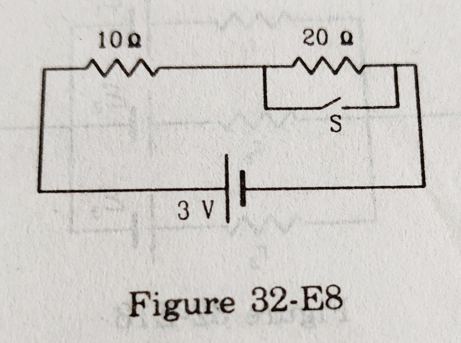
ANSWER: (a) When switch S is open, there are two resistors 10 Ω and 20 Ω connected in series. The equivalent resistance of these two resistances =10+20 =30 Ω.
The potential difference across it = 3 V.
Hence, the current in the circuit
= 3/30 =0·1 A.
Since 10 Ω is in series, the same current 0·1 A will flow through it.
(b) When the switch S is closed, the current through 10 Ω will not enter to 20 Ω and only one resistor 10 Ω remains in the circuit.
Hence, the current through 10 Ω resistor
=3/10 A =0·3 A.
33. Find the currents through the three resistors shown in Figure (32-E9).
Diagram for Q-33

ANSWER: The 4 Ω resistor is bypassed, hence the current through it will always be zero. Now only 4 Ω and 6 Ω resistors remain in the circuit and the same current i will flow through each of them. Equivalent resistance R =4+6 =10 Ω. Since the two cells connected in series are reversely connected, net emf =4-2 =2 V.
The current in the circuit,
i =2/10 =0·2 A.
Hence, 0·2 A current will flow through each of 4 Ω and 6 Ω resistances.
34. Figure (32-E10) shows a part of an electric circuit. The potentials at points a, b and c are 30 V, 12 V and 2 V, respectively. Find the currents through the three resistors. 
The figure for Q-34

ANSWER: Let the current through the 10 Ω resistor =i. The potential drop across it =i*10 =10 i volts. Hence, the potential at the junction of resistors =Vₐ-10i =30-10i volts.
Potential difference across 20 Ω
=30-10i-12 =18-10i volts.
Current through it, i' =(18-10i)/20 A
Potential difference across 30 Ω resistor
=30-10i-2 =28-10i volts.
Current through it, i" =(28-10i)/30 A
From the Kirchoff's junction law
i'+i" =i
→(18-10i)/20 +(28-10i)/30 =i
→{3(18-10i)+2(28-10i)}/60 =i
→60i =54-30i+56-20i
→60i =110-50i
→110i =110
→i =110/110 =1 A.
Hence i' =(18-10*1)/20 =8/20 =0·4 A.
andi" =(28-10*1)/30 =18/30 =0·6 A.
So the current through 10 Ω =1 A, through 20 Ω =0·4 A and through 30 Ω =0·6 A.
35. Each of the resistors shown in Figure (32-E11) has a resistance of 10 Ω and each of the batteries has an emf of 10 V. Find the currents through the resistors a and b in the two circuits. 
The figure for Q-35

ANSWER: In figure (a), resistor a has a potential difference of 10 V across it.
Resistance of a = 10 Ω. Hence current through it,
i =(10 V)/(10 Ω) =1 A.
The potential difference across b
=10 V-10V
=0
Hence, current through b =zero.
In figure (b), the potential difference across a =10 V.
Resistance of a = 10 Ω.
Hence, current through a
=(10 V)/(10 Ω)
=1 A.
Potential difference across b =10-10 =0 V.
Hence, current through b = zero.
36. Find the potential differences Vₐ-Vᵦ in the circuits shown in Figure (32-E12).
The figure for Q-36

ANSWER: Consider figure (a) on the left. Let current i₁ in R₁ towards the left and current i₂ in R₂ towards the left. Then the current in R₃ is i₁+i₂ towards the right (considering the junction point b).
Applying Kirchhoff's voltage law in a loop. Going anticlockwise in the upper loop.
(i₁+i₂)R₃+i₁.R₁-Ԑ₁ =0 ---- (i)
Similarly, clockwise in the lower loop,
(i₁+i₂)R₃+i₂.R₂ -Ԑ₂ =0 ----- (ii)
Subtracting (ii) from (i), we get,
i₁R₁-i₂R₂-Ԑ₁+Ԑ₂ =0
→i₁R₁-i₂R₂ =Ԑ₁-Ԑ₂ ----- (iii)
Adding (i) and (ii), we get,
2(i₁+i₂)R₃+i₁.R₁-Ԑ₁+i₂R₂-Ɛ₂=0
→(R₁+2R₃)i₁+(R₂+2R₃)i₂=Ɛ₁+Ɛ₂ ---(iv)
We solve it for i₁ and i₂.
Multiply (iii) by (R₂+2R₃) and multiply (iv) by R₂, then add. We get,
i₁R₁(R₂+2R₃)+i₁R₂(R₁+2R₃)=(Ɛ₁-Ɛ₂)(R₂+2R₃)+(Ɛ₁+Ɛ₂)R₂
→i₁(2R₁R₂+2R₁R₃+2R₂R₃)=R₂(Ɛ₁-Ɛ₂+Ɛ₁+Ɛ₂)+2R₃(Ɛ₁-Ɛ₂)
→2i₁(R₁R₂+R₂R₃+R₃R₁)=2R₂Ɛ₁+2R₃Ɛ₁-2R₃Ɛ₂
→2i₁(R₁R₂+R₂R₃+R₃R₁)=2(R₂+R₃)Ɛ₁-2R₃Ɛ₂
→i₁={2(R₂+R₃)Ɛ₁-2R₃Ɛ₂}/{2(R₁R₂+R₂R₃+R₁R₃)}
Similarly, we can find out
i₂={2(R₁+R₃)Ɛ₂-2R₃Ɛ₁}/{2(R₁R₂+R₂R₃+R₃R₁)}
Hence,
i₁+i₂ =(R₁Ɛ₂+R₂Ɛ₁)/(R₁R₂+R₂R₃+R₃R₁)
Now, Vₐ-Vᵦ=(i₁+i₂)R₃
=(R₁Ɛ₂+R₂Ɛ₁)R₃/(R₁R₂+R₂R₃+R₃R₁)
Dividing numerator and denominator by R₁R₂R₃, we get
Vₐ-Vᵦ=(Ɛ₁/R₁+Ɛ₂/R₂)/(1/R₁+1/R₂+1/R₃)
The circuit in Figure (b) is the same as in (a) except that between a and b, resistor R₁ is left to Ɛ₁, but we shall get the same set of equations. Hence, the answer is the same.
37. In the circuit shown in figure (32-E13), Ԑ₁ =3 V, Ԑ₂ =2 V, Ԑ₃ =1 V and r₁ =r₂ =r₃ =1 Ω. Find the potential difference between points A and B and the current through each branch. 
The figure for Q-37

ANSWER: Let the current through r₁ and r₃ be i₁ and i₃ towards the left, respectively. The current through r₂ is i₂ towards the right.
Applying Kirchhoff's loop law anticlockwise in the upper loop, we get
i₁r₁+i₂r₂+Ɛ₂-Ɛ₁ =0
→i₁r₁+i₂r₂ =Ɛ₁-Ɛ₂
→i₁+i₂ =1, -----(i)
{after putting the values}
In the lower loop, clockwise
i₂r₂+Ɛ₂-Ɛ₃+i₃r₃ =0
→i₂r₂+i₃r₃ =Ɛ₃-Ɛ₂
→i₂+i₃ = -1
→-i₃ =1+i₂
At junction A,
i₁+i₃ =i₂
→i₁-i₂ =-i₃ = 1+i₂
→i₁-2i₂ = 1 ------ (ii)
Subtract (ii) from (i)
3i₂ = 0
→i₂ = 0.
Considering the middle resistor and cell, the potential difference between A and B,
=i₂r₂ +Ɛ₂ = 0+2 =2 V.
From (ii),
i₁ = 1 A.
Since i₂+i₃= -1,
i₃ = -1 A.
38. Find the current through the 10 Ω resistor shown in Figure (32-E14).

The figure for Q-38

ANSWER: Suppose the current in all the resistors is from left to right. We denote the current in the 3 Ω resistor =i₁, in the 6 Ω resistor =i₂ and in the 10 Ω resistor =i₃. Applying Kirchhoff's junction law at the junction of three resistors, we get
i₁ =i₂ +i₃
Considering the voltage drop in the lower loop clockwise,
i₁*3+i₂*6 -4.5=0
→i₁+2i₂ =1.5
→i₂+i₃+2i₂ =1.5
→3i₂ +i₃ = 1.5
→3i₂ =1.5-i₃ ---------- (i)
Considering the voltage drop in the upper loop clockwise,
i₃*10+3-i₂*6 =0
→6i₂-10i₃ =3
→3 -2i₃-10i₃ =3
→12i₃ = 0
→i₃ = 0.
Hence, the current through the 10 Ω resistor is zero.
39. Find the current in the three resistors shown in Figure (32-E15). 
The figure for Q-39

ANSWER: Assume that the current in three resistors from left to right is i₁, i₂ and i₃ all downwards. Consider the left loop for voltage drop clockwise (Kirchhoff's Voltage Law).
2 +i₁*1-2 = 0
→i₁ =0.
Similarly, in the middle loop clockwise,
2+i₂*1-2-i₁*1 =
→i₂ =i₁ =0.
Going clockwise in the right loop,
2+i₃*1-2-i₂*1 =0
→i₃ =i₂ = 0.
Hence, the current in all three resistors is zero.
40. What should be the value of R in figure (32-E16) for which the current in it is zero? 
The figure for Q-40

ANSWER: The connections of the four resistors are like a Wheatstone bridge, only there is a resistor R in place of a galvanometer. For the current in R to be zero, the bridge should be balanced, i.e. the ratio of the upper two resistors is equal to the ratio of the lower two resistors. Here we see that the ratio of the upper two resistors =10 Ω/5 Ω =2:1 and the ratio of the lower two resistors =10 Ω/5 Ω =2:1.
Both ratios are the same, hence the bridge is balanced. Therefore, there will be no current through R, whatever be the value of the resistance of R.
41. Find the equivalent resistance of the circuits shown in Figure (32-E17) between points a and b. Each resistor has a resistance r. 
Figure for Q-41

ANSWER: The figure in (a) may be rearranged as below, 
The diagram for Q-41(a)

The upper four resistors 1 to 5 are arranged in a balanced Wheatstone bridge, hence the current will never pass through resistor 5. The resistor 5 is not working. Hence, now the equivalent resistance of 1 and 2 =2r, and that
of 3 and 4 =2r. Thus, the resistances 2r, 2r and r are in parallel and their equivalent resistance R between a and b is given as
1/R =1/2r +1/2r +1/r
→1/R =(1+1+2)/2r
→1/R =4/2r =2/r
→R =r/2.
For figure (b), let us name the resistors and assume that a current i enters point a and the same current i exits at b as shown in the figure below:-
Naming of resistors
Considering the symmetry at points a and b, we assume that the current i at a divides into i₁, i₂ and i₁ in resistors 1, 3 and 2, respectively. Similarly, current in resistors 10, 12 and 11 will be i₁, i₂ and i₁ respectively. Now the current in resistor 1 divides as i₃ and i₄ into resistors 4 and 6, respectively. So

i₃+i₄ =i₁.
Since the current in resistor 10 =i₁, the current in resistor 5 = i₁-i₄ =i₃, away from center O. We can assume that the current i₃ coming towards O in resistor 4 enters in resistor 5 as if their junction is not connected at O. Similarly we can assume that a current i₃ in resistor 7 coming towards O enters the resistor 8 and move away from O as if the junction of resistors 7 and 8 is not connected at O. And the current i₂ in resistor 3 goes straight through the resistor 12. Now a simplified diagram can be drawn as below:-
Simplified diagram

Equivalent resistance R' of resistances 4, 5 and 6,
1/R' =1/r +1/2r =3/2r
→R' =2r/3,
Similarly equivalent resistance of resistances 7, 8 and 9 =R' =2r/3.
Equivalent resistance R" of resistance 3 and 12 (in series) =R" =2r.
Now the resistances are arranged in three rows between a and b. In the upper and lower rows, the resistances in series are r, R' and r. Its equivalent resistance R* =r+R'+r =2r+ 2r/3
→R* =8r/3.
In the middle row, there is resistance R" =2r.
So between and b, resistances R*, R" and R* are in parallel. Their equivalent resistance R is given as,
1/R =1/R* +1/R" +1/R*
→1/R =2/R* +1/R"
→1/R =2/(8r/3) +1/2r
→1/R =3/4r +1/2r =5/4r
→R =4r/5.
42. Find the current measured by the ammeter in the circuit shown in Figure (32-E18). 
Figure for Q-42

ANSWER: First, let us name the junctions and resistors as below,
Naming Junctions and Resistors
Suppose the current measured by the ammeter =i. So current i enters at junction A and exits at junction D. From symmetry the current in each of the resistors 1, 2, 5 and 6 will be the same, say i₁. This will make potentials at B and F the same = Va-i₁*10. So there is no potential difference between B and F, thus no current in resistor 7.

Similarly, the potentials at points C and E will be the same = Vd+i₁*10. Hence no potential difference across resistor 8 and no current through it.
Thus we conclude that the current through resistors 3 and 4 will be i₁ each. Now the given combination may be drawn without resistors 7 and 8. This will make the arrangement of resistors as if 1, 3 and 5 in series, with equivalent resistance =10 Ω +10 Ω +10 Ω =30 Ω. Similarly, the resistors 2, 4 and 6 in series with an equivalent resistance =30 Ω.
Finally, the arrangement between A and D becomes two resistances, each of 30 Ω in parallel. Thus, the equivalent resistance of the whole arrangement R is given as,
1/R = 1/30 +1/30 =2/30 =1/15
→R =15 Ω.
The potential difference across A and D =6 V, hence the reading in the ammeter will be
i =6/15 A =0·4 A.
43. Consider the circuit shown in Figure (32-E19a). Find (a) the current in the circuit. (b) the potential drop across the 5 Ω resistor, (c) the potential drop across the 10 Ω resistor. (a) Answer the parts (a), (b) and (c) with reference to figure (32-E19b). 
The figure for Q-43

ANSWER: Figure (a)
(a) Assume the current in the circuit anticlockwise = i. Apply Kirchhoff's loop law anticlockwise.
-6 +i*5 -12 +i*10 = 0
→15i = 18
→ i = 18 /15 A =6/5 A =1·2 A.
(b) The potential drop across 5 Ω resistor = i*5 =1·2*5 V =6 V.
(c) The potential drop across 10 Ω resistor = i*10 =1·2*10 V =12 V.
Figure (b)
(a) We can solve it like figure (a) but it can also be solved as below.
The cells are connected in series; the total potential difference across the cells =12+6 =18 V. The 10 Ω and 5 Ω resistors are connected in series, hence their equivalent resistance R =10+5 =15 Ω.
Since the cells provide a potential difference of 18 V across the resistors, the current through them (current in the circuit),
i =18/15 A =1·2 A.
(b) The potential drop across 5 Ω resistor =5*i =5*1·2 V = 6 V.
(c) The potential drop across 10 Ω resistor =10*i =10*1·2 V = 12 V.
44. Twelve wires, each having equal resistance r, are joined to form a cube as shown in Figure (32-E20). Find the equivalent resistance between the diagonally opposite points a and f. 
The figure for Q -44

ANSWER: Let the equivalent resistance between the diagonally opposite points a and f = R. Suppose a current I enters at point a of the cube and the same current exits at f. From symmetry, the current at the junction a will be equally distributed in three connected resistors. Suppose in each of the resistors ab, ad and ah a current i flows. Thus, I =3i.
Similarly, in each of the resistors cf, ef and gf a current i will flow towards the junction f. And the current 3i =I will exit out of the arrangement at f.
Again from symmetry, the current i in ab will get equally divided to flow as i/2 each in bc and be. Again, the current i in ad will get equally divided to flow as i/2 each in dc and dg. And the current i in ah will get equally divided to flow as i/2 each in he and hg. We draw a diagram depicting these currents in the corresponding resistors. 
The diagram for Q-44

Assume that the potential difference across points a and f is V being maintained by cell B. Now apply Kirchhoff's loop law in the loop abcfBa. We go anticlockwise.
ir + (i/2)r +ir -V =0
→V =(2i+i/2)r =(5/2)ri
But we have I = 3i, →i =I/3, hence
V = (5/2)r*(I/3)
→V =(5r/6)*I.
→V = R*I.
Hence, the equivalent resistance R =5r/6.
45. Find the equivalent resistances of the networks shown in Figure (32-E21) between points a and b. 
The figure for Q - 45

ANSWER: (a) Let us name the upper two junctions as c and d. Between junctions c and b, resistors cd and db are in series, thus equivalent to 2r. Now, this 2r is connected in parallel to the resistor cb resistance of which is r. Now equivalent resistance r' of 2r and r is given as
1/r' =1/r +1/2r =3/2r
→r' =2r/3.
So the resistances cd, db and cb is replaced with equivalent resistance r' =2r/3 and the given arrangement simplifies to diagram (A) as shown below. 
Diagram for Q-45(a)

Now ac and cb are in series, which is equivalent to
r" =2r/3 +r =5r/3
The diagram further simplifies to (B) in which r" =5r/3 and r are in parallel between a and b. The equivalent resistance R between a and b is given as
1/R = 1/r" +1/r
→1/R = 1/(5r/3) +1/r
→1/R =3/5r +1/r
→1/R =(3+5)/5r =8/5r
→R =5r/8.
(b) Let us name the resistors and junctions as below. The resistors 1, 2 and 3 are in a parallel connection between points b and O. 
The diagram for Q-45(b)

Hence the equivalent resistance r' of these three resistors will be,
r' =r/3.
So the given arrangement now simplifies to diagram (B) in which r' and r are connected in series. Hence, the equivalent resistance of the given arrangement of resistors between a and b is
R = r' +r =r/3 +r
→R = 4r/3.
(c) Let us name the junctions and resistors as below:- 
The diagram for Q-45(c)
Since the resistance of each of the resistors is the same and equal to r, the resistors 1, 2, 3 and 4 in the given arrangement between a and b make a balanced Wheatstone bridge. Hence, there will be no current in resistors 5 and 6 and these two will be ineffective.

The given arrangement now simplifies to diagram (B). The equivalent resistance of resistors 1 and 2 = 2r. Similarly, the equivalent resistance of resistors 3 and 4 = 2r. Thus, between a and b, resistances 2r and 2r are connected in parallel. Hence, the equivalent resistance R is given as
1/R =1/2r +1/2r =1/r
→R = r.
(d) We can see that each of the resistors r is connected between points a and b. Hence, four resistors, each of resistance r are connected in parallel between a and b. Thus, the equivalent resistance R is given as
1/R =4/r
→R =r/4.
(e) Let us name the resistors and the joints as follows:- 
The diagram for Q-45(e)
On simplification, the given arrangement of resistors in diagram (A) becomes as in diagram (B). In B, the resistors are actually in a balanced Wheatstone bridge. Thus, no current in the branch cd and resistor 3 becomes ineffective.

Out of four resistors, 2 and 4, as well as 1 and 5, are in series between points a and b. The equivalent resistance of each pair =2r. Finally, between points a and b, two resistors, each of resistance 2r are in parallel combination. The equivalent resistance of this system R is given as,
1/R =1/2r +1/2r
→1/R =1/r
→R = r.
46. An infinite ladder is constructed with 1 Ω and 2 Ω resistors as shown in Figure (32-E22). (a) Find the effective resistance between points A and B. (b) Find the current that passes through the 2 Ω resistor nearest to the battery. 
The figure for Q-46

ANSWER: (a) Let us assume that the equivalent resistance between the points A and B is R. Since the similar arrangement is infinite, the equivalent resistance between corresponding points in the next loop will also be R. Now the infinite series simplifies to the arrangement shown below.
The diagram for Q-46

In this arrangement, R and 2 Ω resistors are in parallel between points C and D. Hence, the equivalent resistance between points C and D =2R/(R+2)
Thus the equivalent resistance between A and B = 2R/(R+2) +1
=(2R+R+2)/(R+2)
=(3R+2)/(R+2)
But we have assumed that the equivalent resistance between points A and B = R. Thus,
(3R+2)/(R+2) =R
→3R+2 =R²+2R
→R² -R -2 =0
→R² -2R +R -2 =0 --- (i)
→R(R-2) +(R-2) =0
→(R+1)(R-2) =0
Either R+1 =0 or R-2 =0.
Thus, either R =-1 or R =2.
Since we can not take R negative, so R =2 Ω.
Note: In (i) above, the factorization technique of the quadratic equation has been discussed in my blog post → A simple trick to factorize a quadratic expression in algebra.
(b) Suppose the current supplied by the battery = i and the current in the 2 Ω resistor nearest to the battery =i'.
i = 6/R =6/2 A =3 A.
At point C, the current i divides to i' in 2 Ω resistor and i-i' in R. Since the value of R is also 2 Ω, the current in 2 Ω and R will be equal, i.e. =i/2 =3/2 A =1·5 A.
47. The emf Ɛ and the internal resistance r of the battery shown in Figure (32-E23) are 4.3 V and 1.0 Ω, respectively. The external resistance R is 50 Ω. The resistance of the ammeter and the voltmeter are 2·0 Ω and 200 Ω, respectively. (a) Find the reading of the two meters. (b) The switch is thrown to the other side. What will be the readings of the two meters now? 
The figure for Q-47

ANSWER: (a) In the given figure, when the switch is left, the resistance of the voltmeter and R are in parallel. Their equivalent resistance r',
1/r' =1/200 +1/50
→1/r' =(1+4)/200
→1/r' =5/200 = 1/40
→r' =40 Ω
Now the resistance of ammeter 2 Ω, r' (=40 Ω) and the internal resistance of the battery r =1 Ω are connected in series. The equivalent resistance of the circuit,
R =2 +40 +1 =43 Ω.
Ɛ = 4·3 V
Hence, the current supplied by the battery, i = Ɛ/R =4·3/43 A
→i = 0·1 A.
This will be the current going through the ammeter. Hence, the reading of the ammeter = 0·1 A.
Suppose a part of this current =i' goes through R and i-i' through the voltmeter. The potential drop across R and the voltmeter will be the same. Hence,
i'R = (i-i')*200
→50i' =200i -200i'
→250i' =200i =200*0·1
→250i' =20
→i' = 20/250 A =0·08 A.
So the potential difference across R or V is = i'*R =0·08*50 = 4 V. So the reading of the voltmeter = 4 V.
(b) When the switch is thrown to the other side, the resistance of the ammeter and R comes in series connection. Their equivalent resistance =50 Ω +2 Ω =52 Ω.
This 52 Ω and the resistance of voltmeter 200 Ω are now in parallel connection. Its equivalent resistance r' is given as
1/r' =1/52 +1/200
→1/r' =(50+13)/2600
→1/r' =63/2600
→r' =2600/63 Ω =41·3 Ω
With an internal resistance of battery 1 Ω, the total external resistance of the circuit R =41·3 +1 =42·3 Ω.
Hence, the current supplied by the battery, i =Ɛ/R =4·3/42·3 ≈0·1 A.
A part of this current = i' goes through the voltmeter and the rest part =i-i' goes through the ammeter + R =r" (say). The potential difference across V and r" will be the same. Hence,
i'*200 =(i-i')*52
→200i' =52i -52i'
→i' = 52i/252 = 52*0·1/252
→i' =0·02 A.
The reading in the ammeter will be i-i' =0·1 -0·02 =0·08 A.
The reading in the voltmeter will be = i'*200 = 0·02*200 V =4 V.
48. A voltmeter of resistance 400 Ω is used to measure the potential difference across the 100 Ω resistor in the circuit shown in Figure (32-E24). (a) What will be the reading of the voltmeter? (b) What was the potential difference across 100 Ω before the voltmeter was connected? 
The figure for Q-48

ANSWER: (a) Given, Ɛ = 84 V. External resistance in the circuit:-
R₁ =100 Ω, R₂ =200 Ω, Resistance of the voltmeter R₃ =400 Ω.
R₁ and R₃ are connected in parallel; their equivalent resistance R' is given as,
1/R' =1/R₁ +1/R₃
→1/R' =1/100 +1/400
→1/R' =5/400 =1/80
→R' =80 Ω.
R' and R₂ are in series connection. Total equivalent external resistance in the circuit, R =R' +R₂ =80+200 =280 Ω.
Hence, the current in the circuit,
i =Ɛ/R =84/280 A =0·3 A
Suppose the voltage drop across R' =V, then V =Ɛ -iR₂
→V =84 -0·3*200 =24 volts.
Hence, the reading of the voltmeter will be 24 V.
(b) Before the connection of the voltmeter, only two resistances R₁ and R₂ are connected in series in the circuit. The equivalent resistance in the circuit,
R =R₁ +R₂ =100+200 =300 Ω
Hence, the current in the circuit,
i =Ɛ/R =84/300 A
→i =0·28 A
This current i will go through both the resistors. Hence, the potential difference across 100 Ω resistor,
=iR₁ =0·28*100 =28 V.
49. The voltmeter shown in Figure (32-E25) reads 18 V across the 50 Ω resistor. Find the resistance of the voltmeter. 
The figure for Q-49

ANSWER: Since the voltmeter and the 50 Ω resistor are connected in parallel, the potential difference across both of them will be equal i.e. =18 V. Let the resistance of the voltmeter = R.
The potential difference across 24 Ω will be =30 -18 =12 V.
Hence, the current through 24 Ω,
i =12/24 =0·5 A.
This current will be divided to go through the 50 Ω resistor and the voltmeter. Since the potential difference across 50 Ω resistor =18 V, the current in 50 Ω resistor will be, i' =18/50 =0·36 A.
Thus the current through the voltmeter, i" = i -i' =0·50 -0·36 =0·14 A.
The potential difference across the voltmeter =18 V.
Hence, the resistance of the voltmeter,
R =18/0·14 ≈ 130 Ω.
50. A voltmeter consists of a 25 Ω coil connected in series with a 575 Ω resistor. The coil takes 10 mA for full-scale deflection. What maximum potential difference can be measured on this voltmeter?
ANSWER: At the maximum measured potential difference V' (say), the current in the coil, i =10 mA =0·01 A.
The coil (r =25 Ω) is connected in series with a resistor (r' =575 Ω). Hence, the same current i =0·01 A will go through it. The equivalent resistance of coil and resistor R = r +r'
→R = 25 +575 = 600 Ω.
Hence, the potential difference across R,
=iR =0.01*600 =6 V.
Thus, the voltmeter can measure a maximum potential difference of 6 V.
51. An ammeter is to be constructed which can read currents up to 2·0 A. If the coil has a resistance of 25 Ω and takes 1 mA for full-scale deflection, what should be the resistance of the shunt used?
ANSWER: At the full-scale deflection, the current in the ammeter i' = 1 mA = 0·001 A. Resistance of the coil, r =25 Ω. Hence, the potential difference across the coil =i'*r = 0·001*25 =0·025 V.
Maximum current to be measured, i =2·0 A. From this current i' =0·001 A is diverted to the ammeter coil, and the rest i" =i -i' is diverted to the shunt.
Let the resistance of the shunt =R, then, R =0·025/(i -i')
→R =0·025/(2·0-0·001)
= 0·0125 Ω
=1·25x10⁻² Ω.
52. A voltmeter coil has a resistance of 50.0 Ω and a resistor of 1.15 kΩ is connected in series. It can read potential differences up to 12 volts. If this same coil is used to construct an ammeter that can measure currents up to 2.0 A, what should be the resistance of the shunt used?
ANSWER: The equivalent resistance of the coil and the resistor R
=50 +1·15x10³ Ω =1200 Ω.
It can read a potential difference of 12 V. At this potential difference, the current through the coil and resistor,
i' = 12/1200 =0·01 A.
So the coil can take a maximum current of 0.01 A. At the maximum current (to be measured), the potential difference across the coil,
E' =i'*50 =0.01*50 =0·5 V.
This potential difference will also be for the shunt of the ammeter to be constructed. Since the ammeter has to measure a current of 2·0 A, out of this the coil takes a current of 0.01 A, so the shunt has to carry a current of,
i" =i -i' =2·0 -0·01 A
→i" =1·99 A.
Hence, the resistance of the shunt should be, R =E'/i"
→R =0·5/1·99 = 0·251 Ω.
53. The potentiometer wire AB shown in Figure (32-E26) is 40 cm long. Where should the free end of the galvanometer be connected on AB so that the galvanometer may show zero deflection? 
The figure for Q-53

ANSWER: Suppose the point where the free end of the galvanometer touches AB for zero deflection is C. Now the resistances 8 Ω, 12 Ω, AC and CB make a balanced Wheatstone bridge. The wire AB is uniform, hence its resistance is proportional to the length. Suppose the resistance of the wire is k per unit length, then the resistance of length AC =k·AC and that of CB =k·CB.
For the above balanced Wheatstone bridge,
k·AC/k·CB =8/12
→AC =CB*2/3
{But CB =AB-AC =40 -AC cm}
→AC =(40 -AC)*2/3
→3AC =80 -2AC
→5AC =80
→AC =80/5 =16 cm.
So for the zero deflection in the galvanometer, the free end of it should be connected at a point 16 cm from end A on AB.
54. The potentiometer wire AB shown in Figure (32-E27) is 50 cm long. When AD = 30cm, no deflection occurs in the galvanometer. Find R. 
The figure for Q-54

ANSWER: AB =50 cm, AD =30 cm, hence DB =50 -30 =20 cm.
The wire AB has a uniform section, and its resistance is proportional to its length. The arrangement given in the figure is a balanced Wheatstone bridge, hence the four resistances are proportional. Thus,
AD/DB = 6/R
→30/20 =6/R
→R =6*2/3 =4 Ω.
55. A 6-volt battery of negligible internal resistance is connected across a uniform wire AB of length 100 cm. The positive terminal of another battery of emf 4 V and internal resistance 1 Ω is joined to point A as shown in Figure (32-E28). Take the potential at B to be zero. (a) What are the potentials at points A and C? (b) At which point D of the wire AB, the potential is equal to the potential at C? (c) If the points C and D are connected by a wire, what will be the current through it? (d) If the 4 V battery is replaced by a 7·5 V battery, what would be the answers of parts (a) and (b)? 
The figure for Q-55

ANSWER: (a) The potential at B is the same as the potential of the negative terminal of the 6 V battery; here, it is given as zero. The potential of the positive terminal of the 6 V battery is the same as that of point A. Since the potential of the positive terminal of the 6 V battery is 6 V higher than the negative terminal (and point B), the potential at A is 6 V.
Now the potential of the positive terminal of the 4 V battery is also the same as A, i.e. 6 V. Since point C is free, there is no current in this branch. The negative terminal and C are at a potential 4 V lower than the positive terminal. Hence, the potential at C =6 V -4 V =2 V.
(b) The resistance of the uniform wire AB is proportional to its length. Hence potential from A (6 V) to B (zero) decreases uniformly. The potential of D is equal to the potential of C =2 V. Thus,
BD/AB = 2/6
→BD =AB/3 =100/3 =33·33 cm.
Hence AD =100 -33·33 =66·7 cm.
So the required point is 66·7 cm from A.
(c) As given in (b), the potentials of D and C are the same. Hence, there is no potential difference between them. It means no current through the connected wire CD. Zero.
(d) When the 4 V battery is replaced by a 7.5 V battery.
There will be no change in the potential of A, which is at 6 V. The positive terminal of the new battery and A are at the same potential i.e. at 6 V but the negative terminal and C are now at a potential 7·5 V less than A and the positive terminal of the new battery. Hence, the potential of C =6 V -7·5 V = -1·5 V.
Since the potential on AB varies from zero to 6 V, from B to A, there is no point D on AB that has a potential of -1·5 V (equal to C).
56. Consider the potentiometer circuit arranged as in Figure (32-E29). The potentiometer wire is 600 cm long. (a) At what distance from point A should the jockey touch the wire to get zero deflection in the galvanometer? (b) If the jockey touches the wire at a distance of 560 cm from A, what will be the current in the galvanometer? 
The figure for Q-56

ANSWER: (a) The total resistance of the circuit =r +15r = 16r.
The current in the circuit, i =Ɛ/16r.
If we assume the potential at B to be zero, then the potential of the negative plate of the battery = 0-ir =-ir,
=-Ɛr/16r = -Ɛ/16.
And the potential of the positive terminal of the battery (as well as that of A) =Ɛ +(-Ɛ/16) =15Ɛ/16.
So the potential from B to A uniformly varies at the rate of α =15Ɛ/(16*600) volts per centimeter.
There is no current in the lower branch and the potential of the positive terminal of the battery having emf Ɛ/2 is the same as that of A =15Ɛ/16. Thus the potential from the negative terminal of this battery to the jockey
=15Ɛ/16 -Ɛ/2
=(15Ɛ -8Ɛ)/16
=7Ɛ/16.
To get a zero deflection in the galvanometer, the point where the jockey will touch the wire should have the same potential as the jockey, i.e. =7Ɛ/16.
The rate of variation of the potential on the wire is α = 15ℰ/(16*600). Hence the point on AB having a potential of 7ℰ/16 from B = (7ℰ/16)÷(15ℰ/(16*600) cm
=7ℰ*16*600/(15ℰ*16) cm
=7*600/15 cm
=7*40 cm
=280 cm.
Hence, the distance of this point from A =600-280 cm =320 cm.
(b) When the jockey touches the wire at 560 cm from A, there will be a current in the lower loop. Also, the current in the upper loop will change. Let us draw a diagram as follows:- 
The diagram for Q-56b

Point D divides the wire into two resistances. Resistance of the part AD =(560/600)*15r
=14r.
Resistance of the other part DB =15r-14r =r.
Let the current in the galvanometer =i'.
The current in AD =i" and the current in DB =i as shown in the diagram.
With Kirchhoff's junction law at A,
i =i' +i".
Let us apply loop law in the upper loop anticlockwise,
ir +ir -ℰ +i"*14r =0
→14i"r +2ir =ℰ
→14i"r +2i'r +2i"r =ℰ
→16i"r =ℰ-2i'r
→i" =(ℰ-2i'r)/16r
In the lower loop,
ℰ/2 +i'r -i"*14r =0
→i'r -14i"r +ℰ/2 =0
→i'r -(14rℰ -28i'r²)/16r +ℰ/2 =0
→16i'r² -14rℰ +28i'r² +8rℰ = 0
→44i'r² -6rℰ =0
→r(22i'r -3ℰ) =0
Since r is not zero, hence,
221i'r -3ℰ =0
→i' =3ℰ/22r.
So the current in the galvanometer will be =3ℰ/22r.
57. Find the charge on the capacitor shown in the figure (32-E30). 
The figure for Q-57

ANSWER: The potential difference across the capacitor will be the same as the potential difference across the 10 Ω resistor. The 10 Ω resistor and the 20 Ω resistor are connected in series. The equivalent resistance R =10 +20 =30 Ω. ℰ =2 V.
Hence, the current in the circuit,
i =2/30 =0·067 A.
So the current through the 10 Ω resistor is 0·067 A. Hence, the potential difference across 10 Ω resistor = i*10
=0·067*10 =0·67 V.
It is also the potential difference across the capacitor. Capacitance, C = 6 µF.
Hence, the charge on the capacitor,
Q =CV =(6 µF)*(0·67 V)
→Q =4.02 µC ≈4 µC.
58. (a) Find the current in the 20 Ω resistor shown in Figure (32-E31). (b) If a capacitor of capacitance 4 µF is joined between points A and B, what would be the electrostatic energy stored in it in a steady-state? 
The figure for Q-58

ANSWER: (a) From the symmetry, the current in each of the 10 Ω resistors = i (say) in the direction as shown in the diagram. From the junction law at A, the current in 20 Ω resistor, i' =2i, i.e. i =i'/2. 
The diagram for Q-58a

Applying Kirchhoff's loop law in the left loop, clockwise:-
i*10 +i'*20 -5 =0
→10*i'/2 +20i' =5
→25i' =5
→i' =5/25 =0·2 A.
So the current in the 20 Ω resistor =0·2 A.
(b) When a capacitor is joined between points A and B the potential difference across it is the same as the potential difference across the 20 Ω resistor. This potential difference, V =i'*20
→V =0.2*20 =4 volts. 
The diagram for Q-58b

The capacitance of the capacitor (given), C =4 µF.
Hence, the electrostatic energy stored,
E =½CV²
→E =½*4*4² µJ
→E =32 µJ.
59. Find the charges on the four capacitors of capacitances 1 µF, 2 µF, 3 µF, and 4 µF shown in Figure (32-E32). 
The figure for Q-59

ANSWER: We know that in a steady-state, no current flows across the plates of the capacitors. Hence, in the given arrangement, the current supplied by the battery will only go through the resistors. Let us first name the junctions and capacitors for our convenience as follows:-
Ch-32, Q-59

In the upper loop of resistors, a current will flow in the loop AKLBA. The potential difference across KL = 6 V. The equivalent resistance of resistors connected in series between KL = 1+2 =3 Ω. Hence, the current between KL,
i =(6 V)/(3 Ω) =2 A.
The potential of G and K is the same, and also the potential of M and N is the same. Hence, the potential difference across the capacitor ① is the same as the resistor KN, which will be equal to,
V' =i*(1 Ω) =(2 A)*(1 Ω) =2 volts.
Thus, the charge on the capacitor ①,
=(1 µF)*(2 V) =2 µC.
Similarly the potential difference across the capacitor ② = i*(2 Ω) =(2 A)*(2 Ω) =4 V. Hence the charge on the capacitor ② =(2 µF)*(4 V) =8 µC.
Now consider the lower loop AEFBA. The potential difference across CD =6 V.
Equivalent resistance across CD =3 Ω+ 3 Ω =6 Ω. Hence the current in section CD, i' =(6 V)/(6 Ω) = 1 A.
The potential difference across the resistor CP = the potential difference across the capacitor ③ =i'*(3 Ω)
=(1 A)*(3 Ω) = 3 V.
Thus the charge on the capacitor ③,
=(3 µF)*(3 V) =9 µC.
Similarly, the potential difference across the capacitor ④ =i'*(3 Ω) =3 V.
The capacitance of ④ =4 µF,
The charge on the capacitor ④ =4*3 µC
=12 µC.
60. Find the potential difference between points A and B and between B and C of the figure (32-E33) in a steady-state. 
The figure for Q-60

ANSWER: In the given figure all the elements above points A and C are capacitors. In a steady-state, there is no current flow through a capacitor. Hence, the potential of a continuous wire will be the same.
Two 3 µF capacitors are connected in parallel between A and B, Their equivalent capacitance =3 +3 =6 µF. Similarly, two 1 µF capacitors are in parallel between B and C. Their equivalent capacitance =1 +1 = 2 µF. Now the arrangement simplifies as below:-
The diagram for Q-60

Capacitors AB and BC are in series. Their equivalent capacitance C' is given by,
1/C' = 1/6 +1/2 =4/6 =2/3
→C' =3/2 µF.
C' and 1 µF are in parallel hence the total equivalent capacitance,
C =1 +3/2 =5/2 =2·5 µF.
The potential across this equivalent capacitor =100 V. Thus the total charge on this capacitor,
Q =CV =2·5*100 µC =250 µC.
The potential difference across both capacitors C' and 1 µF is 100 V due to the parallel connection. Thus the charge stored on 1 µF capacitor,
q =1*100 =100 µC.
The rest of the charge is on C' i.e.,
q' =Q -q =250 -100 =150 µC.
C' comprises of two capacitors in series whose equivalent capacitances are 6 µF and 2 µF. Since in a series connection the charge on each of the capacitors is the same, hence the charge on the 6 µF capacitor between A and B is also q' =150 µC. Now the potential difference across 6 µF capacitor = The potential between A and B = V' =q'/6 =150/6 V =25 V.
Similarly, the potential difference across 2 µF capacitor = The potential difference between B and C =q'/2 =150/2 V =75 V.
61. A capacitance C, a resistance R and an emf ℰ are connected in series at t = 0. What is the maximum value of (a) the potential difference across the resistor, (b) the current in the circuit, (c) the potential difference across the capacitor, (d) the energy stored in the capacitor, (e) the power delivered by the battery (f) the power converted into heat?
ANSWER: (a) Before connections are made, the whole circuit is at the same potential; suppose these are at zero potential. Once the key K is switched on the positive charge rushes to end B of the resistor, (see diagram below). 
The diagram for Q-61

So at that instant, the potential of end B is ℰ while the end A is still at zero potential. At this instant, the potential difference across the resistor = ℰ. As time passes, the potential of the whole resistor becomes =ℰ and the potential difference across the resistor becomes zero. Thus the maximum value of potential difference across the resistor is = ℰ.
(b) The maximum value of the current,
i = maximum P.D/resistance = ℰ/R.
(c) The right-hand plate of the capacitor will attain the potential of the positive plate of the battery while the left-hand plate will attain the potential of the negative plate of the battery. Thus the maximum potential difference across the capacitor =ℰ.
(d) The maximum value of the energy stored in the capacitor will be at the maximum potential difference ℰ. Thus,
Maximum E =½Cℰ².
(e) The maximum power delivered by the battery, P =ℰ*maximum current
→P = ℰ*ℰ/R = ℰ²/R.
(f) The maximum power converted into heat by the resistor = Maximum Current in the resistor*maximum potential difference across the resistor
= (ℰ/R)*ℰ =ℰ²/R
62. A parallel-plate capacitor with a plate area of 20 cm² and plate separation of 1.0 mm is connected to a battery. The resistance of the circuit is 10 kΩ. Find the time constant of the circuit.
ANSWER: A = 20 cm² =0·002 m², d = 1 mm =0·001 m. Hence, the capacitance,
C = ԑ₀A/d = 8.85x10⁻¹²*0.002/0.001 F
=1·77x10⁻¹¹ F
R =10 kΩ =1x10⁴ Ω
Hence, the time constant of the circuit,
𝜏 =RC =1x10⁴*1·77x10⁻¹¹ s
=1·77x10⁻⁷ s
≈0·18x10⁻⁶ s
=0·18 µs.
63. A capacitor of capacitance 10 µF is connected to a battery of emf 2 V. It is found that it takes 50 ms for the charge on the capacitor to become 12.6 µC. Find the resistance of the circuit.
ANSWER: The charge at time t on a capacitor is given as,
q = ℰC(1 -e-t/RC)
→12·6 =2*10*(1-e-t/RC)
→e-t/RC =1-0·63 =0·37
→-t/RC = ln 0·37 ≈ -1
→RC = t, {Given t =50 ms =0.05 s}
→R =0·05/10x10⁻⁶ Ω
→R = 5000 Ω = 5 kΩ.
64. A 20 µF capacitor is joined to a battery of emf 6·0 V through a resistance of 100 Ω. Find the charge on the capacitor 2·0 ms after the connections are made.
ANSWER: Given ℰ = 6·0 V, C = 20 µF, R =100 Ω, t = 2·0 ms =0·002 s and q = ?
The value of t/RC =0·002/(100*20x10⁻⁶)
= 1
Now,
q = ℰC(1 -e-t/RC)
=6*20(1-e⁻¹) µC
=120*(1-0·37)
=120*0·63 µC
≈76 µC.
65. The plates of a capacitor of capacitance 10 µF, charged to 60 µC, are joined together by a wire of resistance 10 Ω at t = 0. Find the charge on the capacitor in the circuit at (a) t = 0, (b) t = 30 µs, (c) t = 120 µs and (d) t =1.0 ms.
ANSWER: For the discharging capacitor, the charge on it at time t is given as, q =Qe-t/RC, hence
(a) at t = 0, q =Q*1 =Q =60 µC,
(b) at t = 30 µs,
-t/RC =-(30 µs)/(10 Ω*10 µF)
= -0·3
Hence, q =Qe-0·3
=(60 µC)*0·74
=44 µC.
(c) At t = 120 µs,
-t/RC = -(120 µs)/(10 Ω*10 µF)
=-1·2
Hence, q =Qe-1·2
→q =(60 µC)*0·30 = 18 µC.
(d) At t =1.0 ms =0.001 s
-t/RC =-0·001/(10*10x10⁻⁶)
= -10
Hence q =Qe-10
=(60 µC)*4·54x10⁻⁵
≈0·003 µC.
66. A capacitor of capacitance 8·0 µF is connected to a battery of emf 6·0 V through a resistance of 24 Ω. Find the current in the circuit, (a) just after the connections are made and (b) one time constant after the connections are made.
ANSWER: (a) Just after the connections are made, the potential difference across the resistor is maximum and equal to the emf. So V' =6 V, R =24 Ω, hence the current in the circuit,
i =V'/R =6/24 A =0·25 A.
(b) Given C =8·0 µF
Time constant 𝜏 = RC
After one time constant i.e t =RC, the charge on the capacitor,
q = ℰC(1 -e-t/RC)
→q =ℰC(1 -e⁻¹)
→q =6*8*0·63 µC = 30·24 µC
The potential difference across the capacitor, V' =q/C =30·24/8·0 =3·78 V.
Let the current in the circuit = i.
From Kirchhoff's loop law,
iR +V' - ℰ = 0
→i*24 +3·78 -6 =0
→i = 2·22/24 A =0·09 A.
67. A parallel plate capacitor of plate area 40 cm² and separation between the plates 0.10 mm is connected to a battery of emf 2.0 V through a 16 Ω resistor. Find the electric field in the capacitor 10 ns after the connections are made.
ANSWER: Given A =40 cm² =0·004 m², Separation d =0·10 mm =0·0001 m, the emf ℰ =2·0 V, resistance R =16 Ω.
The capacitance C = ԑ₀.A/d
→C = 8·85x10⁻¹²*0.004/0.0001
=3.54x10⁻¹⁰ F
t =10 ns =10x10⁻⁹ s
t/RC =10x10⁻⁹/(16*3·54x10⁻¹⁰)
=1·77
Charge on the capacitor after 10 ns,
q = ℰC(1-e-t/RC)
=2*3·54x10⁻¹⁰(1-e-1·77)
=5·88x10⁻¹⁰ C
The potential difference across the capacitor, V' =q/C
→V' = 5·88x10⁻¹⁰/3.54x10⁻¹⁰
=1.66 V
Hence the electric field in the capacitor,
E =V'/d
=1.66/0.0001 V/m
≈1.7x10⁴ V/m
68. A parallel plate capacitor has a plate area of 20 cm², plate separation 1.0 mm and a dielectric slab of dielectric constant 5·0 filling up the space between the plates. This capacitor is joined to a battery of emf 6·0 V through a 100 kΩ resistor. Find the energy of the capacitor 8.9 µs after the connections are made.
ANSWER: Given A =20 cm² =2x10⁻³ m², d =1·0 mm =1x10⁻³ m, K =5·0. Hence, the capacitance, C =Kԑ₀A/d
→C =5*8.85x10⁻¹²*2x10⁻³/(1x10⁻³)
→C =88.5x10⁻¹² F
→C ≈8.9x10⁻¹¹ F
R =100 kΩ =1x10⁵ Ω
ℰ = 6·0 V
t =8·9 µs =8.9x10⁻⁶ s
t/RC =8·9x10⁻⁶/(1x10⁵*8·9x10⁻¹¹)
=1
The charge on the capacitor after 8.9 µs,
q =ℰC(1 -e⁻¹)
=6*8.9x10⁻¹¹*0.63 C
=3.36x10⁻¹⁰ C
Hence, the energy of the capacitor at this instant,
U =q²/2C
=(3.36x10⁻¹⁰)²/(2*8.9x10⁻¹¹) J
=0.63x10⁻⁹ J
=6.3x10⁻¹⁰ J
69. A 100 µF capacitor is joined to a 24 V battery through a 1.0 MΩ resistor. Plot qualitative graphs (a) between current and time for the first 10 minutes and (b) between charge and time for the same period.
ANSWER: Given C =100 µF =1x10⁻⁴ F, ℰ =24 V, R =1.0 MΩ =1x10⁶ Ω.
RC =1x10⁶*1x10⁻⁴ s
=100 s.
At time t, the charge on the capacitor,
q = ℰC(1 -e-t/RC)
→q =24*1x10⁻⁴(1- e-t/100) --- (i)
→q =24x10⁻⁴ -24x10⁻⁴e-t/100
(a) Final time =10 min =600 s,
The current i =dq/dt
→i = (-24x10⁻⁴e-t/100)*(-1/100)
=24x10⁻⁶*e-t/100
=24x10⁻⁶/et/100
At t =0, i =24x10⁻⁶ A
At t =100 s, i =24x10⁻⁶*0.37 A
At t =200 s, i =24x10⁻⁶*0.14 AAt t =300 s, i =24x10⁻⁶*0.05 AAt t =400 s, i =24x10⁻⁶*0.02 A At t =500 s, i =24x10⁻⁶*0.006 A At t =600 s, i =24x10⁻⁶*0.002 A.The time-current graph will be as follows,
The graph for Q-69(a)
 |
| The graph for Q-69(a) |
(b ) The on the capacitor at time t,
q =24x10⁻⁴(1 -e-t/100) --(i)
At t =0, q = 0,
At t =100 s, q =24x10⁻⁴*0.63 CAt t =200 s, q =24x10⁻⁴*0.86 CAt t =300 s, q =24x10⁻⁴*0.95 CAt t =400 s, q =24x10⁻⁴*0.98 CAt t =500 s, q =24x10⁻⁴*0.994 CAt t =600 s, q =24x10⁻⁴*0.998 CSo at t =600 s the charge is very very close to the capacitance of the capacitor. The graph can be plotted as below:-
The graph for Q-32-69(b)
 |
| The graph for Q-32-69(b) |
70. How many constants will elapse before the current in a charging RC circuit drops to half of its initial value? Answer the same question for a discharging RC circuit.
ANSWER: For a charging circuit, the charge on the capacitor at time t
q =Q(1-e-t/RC)
The current,
i =dq/dt
→i =-Qe-t/RC*(-1/RC)
→i =Q/(RCet/RC)
Current at t = 0,
i' =Q/RC ------------- (i)
Let the current at time t' is i'/2, then
i'/2 =Q/(RCet'/RC) -------- (ii)
Dividing (i) by (ii),
2 =et'/RC
→et'/RC = 2
→t'/RC = ln 2
→t' = 0.69*RC
RC = time constant. So 0.69 time constants will elapse before the current in the circuit drops to half of its initial value.
For the discharging circuit:-
The charge on the capacitor at time t is,
q = Qe-t/RC
The current at time t,
i =dq/dt =-Q/(RCet/RC)
The negative sign is for the direction compared to the charging circuit.
At time t = 0, i' =-Q/RC -----(i)
Let at time t', i =i'/2, then
i'/2 =-Q/(RCet'/RC) ---- (ii)
Dividing (i) by (ii),
2 = et'/RC
→t'/RC = ln2
→t' = (ln 2)*RC
=0.69*Time-constant
So the 0.69 time constant will elapse before the current in the discharging circuit drops to half of its initial value.
71. How many time constants will elapse before the charge on a capacitor falls to 0.1% of its maximum value in a discharging RC circuit?
ANSWER: Suppose the required time is t'.
Maximum charge on a capacitor =Q
At time t the charge on the capacitor is,
q =Qe-t/RC
Here q =(0·1/100)Q =0·001Q
Thus, 0·001Q =Qe-t'/RC
→e-t'/RC =0·001
→-t'/RC = ln(0·001)
→t' = 6·9 RC.
72. How many time constants will elapse before the energy stored in a capacitor reaches half of its equilibrium value in a charging RC circuit?
ANSWER: Let the equilibrium value of charge on the capacitor =Q.
The energy stored in the capacitor at equilibrium, U =Q²/2C, where C is the capacitance of the capacitor.
Suppose the charge on the capacitor at time t when the energy stored is half of the equilibrium value is q. At this time, the energy stored U' =q²/2C.
But, U' = U/2
→q²/2C =Q²/4C.
→q = Q/√2
The number of time constants elapsed to reach this point, n = t/RC.
For a charging circuit,
→q = Q(1 -e-t/RC) =Q(1 -e-n)
→Q/√2 =Q(1 -1/en)
→1/√2 = 1 -1/en
→1/en = (√2-1)/√2
→en =√2/(√2-1) = 3·414
→n =ln 3·414 = 1·23.
73. How many time constants will elapse before the power delivered by the battery drops to half of its maximum in an RC circuit?
ANSWER: In a charging circuit, the charge on the capacitor at time t is given as,
q =ℰC(1 -e-t/RC)
The current at time t,
i = dq/dt = (ℰ/R)e-t/RC
It is clear that the current decreases as time increases. The maximum current is at t=0,
I = ℰ/R,
The maximum power delivered,
P =ℰI =ℰ²/R
Suppose at time t', the power delivered is P/2 and the current in the circuit is i'. The number of time constants, n =t'/RC.
So, i' = (ℰ/R)e-n
Now power delivered by the battery,
=ℰi'
So, P/2 = ℰi'
→ℰ²/2R = (ℰ²/R)*e-n
→en = 2
→n = ln 2 = 0·69.
74. A capacitor of capacitance C is connected to a battery of emf ℰ at t =0 through a resistance R. Find the maximum rate at which the energy is stored in the capacitor. When does the rate have this maximum value?
ANSWER: The energy stored in a capacitor, U = q²/2C.
At time t, q =ℰC(1 -e-t/RC)
Hence U =½ℰ²C(1 -e-t/RC)²
Rate of storage of energy, r =dU/dt
=½*2ℰ²C(1 -e-t/RC)*{-e-t/RC*(-1/RC)}
=(ℰ²/R)e-t/RC*(1-e-t/RC)
For r to be maximum or minimum,
dr/dt =0
→d²U/dt² =0,
→(ℰ²/R){e-t/RC*e-t/RC/RC +(1-e-t/RC)e-t/RC*(-1/RC)}=0
→(1/RC){e-2t/RC -e-t/RC(1-e-t/RC) =0
→e-t/RC{e-t/RC -1 +e-t/RC} =0
→e-t/RC{2e-t/RC -1} =0,
Either, e-t/RC =0,
This gives t =infinity, it is the condition for minimum because the current then is negligible.
Or, 2e-t/RC =1
→e-t/RC = 1/2,
→-t/RC = ln (1/2) = -0.69
→t = 0.69RC
Now the maximum rate of storage of energy,
r =(ℰ²/R)e-0.69*(1-e-0.69)
=(ℰ²/R)*(0.5)²
=ℰ²/4R.
As we have calculated that this maximum rate is at a time,
t =0.69RC =RC.ln2
75. A capacitor of capacitance 12.0 µF is connected to a battery of emf 6.00 V and internal resistance 1.00 Ω through resistance-less leads. 12.0 µs after the connections are made, what will be the (a) the current in the circuit, (b) the power delivered by the battery, (c) the power dissipated in heat, and (d) the rate at which the energy stored in the capacitor is increasing?
ANSWER: ℰ =6.0 V, R =1 Ω, C =12 µF, t =12.0 µs.
(a) The charge on the capacitor at time t is,
q =ℰC(1 -e-t/RC), where Q is the charge at equilibrium.
Hence, the current in the circuit,
i =dq/dt
→i =(ℰ/R)e-t/RC
At t =12 µs,
t/RC =12/(1*12) =1, Thus the current at this time =(6/1)*e⁻¹ =6/e =2·21 A.
(b) The power delivered by the battery at this instant, P = ℰi =6*2·21 W
→P =13·26 W.
(c) As we have derived in Q-74, the rate of energy storage
r =(ℰ²/R)e-t/RC*(1-e-t/RC)
=(6²/1)*(1/e)*(1-1/e)
=8·38 W ----------------- (i)
So the power being stored =8·38 W
The power dissipated in heat,
=13·26 -8·38 =4·88 W.
Alternatively,
The power dissipated in heat is through the resistance of 1 Ω,
=i²R
=(2·21)²*1 W
= 4·88 W.
(d) As calculated in (c) (i) the rate is 8.38 W.
76. A capacitance C charged to a potential difference V is discharged by connecting its plates through a resistance R. Find the heat dissipated in one time constant after the connections are made. Do this by calculating ∫i²Rdt and also by finding the decrease in the energy stored in the capacitor.
ANSWER: The energy stored in the capacitor initially U =½CV².
Charge on the capacitor after time t,
q =CVe-t/RC.
Now the energy remaining,
U' =q²/2C
=(C²V²e-2t/RC)/2C
=½CV²e-2t/R
After one time constant, t/RC =1
→U' =½CV²e⁻²
Hence, the heat dissipated after one time constant =U -U'
=½CV² -½CV²e⁻²
=½(1 -e⁻²)CV².
Alternative method:-
Current in the circuit at time t,
i =dq/dt
=d(CVe-t/RC)/dt
= (-1/RC)CVe-t/RC
=-(V/R)e-t/RC
Hence, the heat dissipated in the circuit,
H =∫i²Rdt
=(V/R)²∫(e-t/RC)²R dt
={(V/R)²*R/(-2/RC)}[e-2t/RC]
=-½CV²[e-2t/RC]
The limit of integration is from t =0 to t =RC. Hence,
H = -½CV²[e⁻² -1]
=½(1 -e⁻²)CV².
77. By evaluating ∫i²Rdt, show that when a capacitor is charged by connecting it to a battery through a resistor, the energy dissipated as heat equals the energy stored in the capacitor.
ANSWER: When a capacitor is fully charged, the energy stored in it is,
U =½Cℰ² ----------------------(i).
For a charging capacitor at any time t, the charge on the capacitor
q = ℰC(1 -e-t/RC)
Current in the circuit, i =dq/dt
→i =(ℰ/R)e-t/RC
The energy dissipated as heat through the resistor, U(H) =∫i²Rdt
=(ℰ²/R)∫e-2t/RCdt
=-(RC/2)(ℰ²/R)[e-2t/RC]
=-½Cℰ²[e-2t/C]
Putting the limits of integration from t =0 to t = ∞ (because theoretically the capacitor will be fully charged at time infinity, though practically after a long time),
U(H) =-½Cℰ²[e-2∞/RC -1]
=-½Cℰ²(0 -1)
=½Cℰ²
It is the same as the energy stored in the capacitor as in (i) = U,
Hence proved.
78. A parallel-plate capacitor is filled with a dielectric material having a resistivity ⍴ and dielectric constant K. The capacitor is charged and disconnected from the charging source. The capacitor is already discharged through the dielectric. Show that the time constant of the discharge is independent of all geometrical parameters, like the plate area or separation between the plates. Find this time constant.
ANSWER: Let the plate area of the capacitor = A and the distance between the plates =d. The capacitance of this capacitor,
C =KԑₒA/d
The dielectric is the resistor through which the capacitor is discharged. It's resistance,
R =⍴(d/A)
The time constant of the discharge,
𝛕 = RC
= ⍴(d/A)*KԑₒA/d
= ԑₒ⍴K.
Clearly, the time constant is independent of all geometrical parameters.
79. Find the charge on each of the capacitors 0.20 ms after the switch S is closed in figure (32-E34). 
The figure for Q-79

ANSWER: Two equal capacitors (each C =2.0 µF) are connected in parallel, hence the equivalent capacitance,
C' = C +C =2C =4.0 µF
ℰ =6.0 V, R =25 Ω.
The charge on the equivalent capacitor after time t =0.20 ms,
Q' =ℰC(1 -e-t/RC)
=6*(4 µF)*(1 -e-{2.0x10⁻⁴/(25x4x10⁻⁶)} µC
=24*(1 -e⁻²) µC
=24(1 -0.14) µC
=20.64 µC
If the charge on each capacitor = q, then,
q =CV, where V is the potential difference across the capacitors.
→C =q/V
And, Q' =C'V,
→C' =Q'/V,
But, C' = 2C
→Q'/V =2q/V
→2q =Q'
→q =Q'/2
=20.64/2 µC
=10.32 µC.
80. The switch S shown in Figure (32-E35) is kept closed for a long time and is then opened at t = 0. Find the current in the middle 10 Ω resistor at t =1·0 ms. 
The figure for Q-80

ANSWER: After a long time, the capacitor is fully charged. When the switch is closed further, the current still flows through both of the resistors.
Suppose the potential difference across the capacitor and the middle 10 Ω resistor =V.
The current in the middle resistor,
i =V/10.
This will also be the current in the lower loop because no current passes through the capacitor. The resistance of the lower loop =10 Ω +10 Ω =20 Ω. (Series connection)
Hence the current in this circuit =12/20 =0·6 A
So V/10 =0.6
→V =6 Volts
The charge on the capacitor,
Q = (25 µF)*(6 V) =150 µC.
When the switch is opened, the battery and the lower 10 Ω resistor are out of the circuit. The charged capacitor is now being discharged through the middle 10 Ω resistor. For a discharging capacitor, the charge remaining on the capacitor,
q =Qe-t/RC
The current in the resistor at time t,
i =dq/dt
=-(Q/RC)e-t/RC
At t =1.0 ms =0.001 s
t/RC =0.001/(10*25x10⁻⁶) =4
i =-{150 µC/(10*25 µF)}e-4
=-0.60*0.018 A
=-0.011 A
=-11 mA.
The negative sign shows the current opposite of the charging direction.
81. A capacitor of capacitance 100 µF is connected across a battery of emf 6·0 V through a resistance of 20 kΩ for 4·0 s. The battery is then replaced by a thick wire. What will be the charge on the capacitor 4·0 s after the battery is disconnected?
ANSWER: emf, ℰ =6.0 volt, R =20 kΩ =2x10⁴ Ω, C = 100 µF =1x10⁻⁴ F, t = 4 s.
t/RC =4/(2x10⁴*1x10⁻⁴)
=4/2 =2
Hence the charge stored on the capacitor after 4.0s,
q =ℰC(1-e-t/RC)
=ℰC(1 -e⁻²)
=6x1x10⁻⁴(1 -0.135) C
=6x10⁻⁴*0.865 C
=5.18x10⁻⁴ C
When the battery is displaced by a thick wire, the capacitor starts discharging. In this case, the charge after time t,
q' =q*e-t/RC
=5.18x10⁻⁴*e⁻²
=5.18x10⁻⁴*0.135 C
=0.70x10⁻⁴ C
=70x10⁻⁶ C
=70 µC.
82. Consider the situation shown in Figure (32-E36). The switch is closed at t =0 when the capacitors are uncharged. Find the charge on the capacitor C₁ as a function of time t. 
The figure for Q - 82

ANSWER: Equivalent capacitance, C of the two capacitors connected in series is given as,
1/C =1/C₁ +1/C₂
→C =C₁C₂/(C₁+C₂)
emf of the battery = ℇ, Resistance through which the capacitors are being charged =r,
Hence, the charge on the equivalent capacitor at time t,
q =ℇC(1 -e-t/rC)
Since the capacitors are connected in series, the same charge will be there on each capacitor. Hence, the charge on capacitor C₁ =q =ℇC(1 -e-t/rC)
where C = C₁C₂/(C₁ +C₂).
83. A capacitor of capacitance C is given a charge Q. At t =0, it is connected to an uncharged capacitor of equal capacitance through a resistance R. Find the charge on the second capacitor as a function of time.
ANSWER: Suppose a charge Q is given to the capacitor A. Then Q = CV, where V is the potential difference across the plates.
After time t, the charge on the 2nd capacitor B = q (say).
Now q =CV', where V' is the potential difference across the capacitor B.
So, V' =q/C.
If the remaining charge on the capacitor A after time t =q', then q' =CV". V" being the potential difference across B after time t. Then, V" = q'/C. 
The diagram for Q-83

Now the potential difference between the plates of A and B after time t = V" -V'.
Hence, the current in the resistance R, =(V" -V')/R. But also current = dq/dt, thus,
dq/dt = (V" -V')/R
=(q'/C -q/C)/R.
=(q' -q)/RC
=(Q-q-q)/RC
=(Q -2q)/RC.
Hence dt/RC = dq/(Q -2q)
Integrating both sides,
[t/RC] = -½*[ln(Q -2q)]
Putting the limits of integration from t =0, q =0 to t = t, q =q.
t/RC =-½[ln(Q -2q) -ln Q]
→-2t/RC =ln[(Q -2q)/Q]
→e-2t/RC =(Q -2q)/Q
→2q = Q -Qe-2t/RC
→q = ½Q(1 -e-2t/RC)
84. A capacitor of capacitance C is given a charge Q. At t =0, it is connected to an ideal battery of emf ℇ through a resistance R. Find the charge on the capacitor at time t.
ANSWER: Suppose, after time t, a charge q remains on the capacitor. The charge flowing out of the capacitor
=Q -q.
The potential difference across the capacitor, V =q/C.
The potential difference between battery and capacitor = V -ℇ
=q/C -ℇ
The current at this instant
=(q/C -ℇ)/R.
The current is the charge flowing out of the capacitor, i =d(Q -q)/dt =-dq/dt
Hence (q/C -ℇ)/R =-dq/dt
→-dt/CR =dq/(q -ℇC)
Integrating both sides,
[-t/CR] =[ln(q -ℇC)]
Limits of integration, at t =0, q =Q.
At t =t, q =q. Let us put these limits.
-t/CR =ln(q -ℇC) -ln(Q -ℇC)
→ln{(q -ℇC)/(Q -ℇC) = -t/CR
→(q -ℇC)/(Q -ℇC) =e-t/CR
→q -ℇC =(Q -ℇC)e-t/CR
→q =ℇC +Qe-t/CR -ℇCe-t/CR
=ℇC(1 -e-t/CR) +Qe-t/CR
It is an interesting result. The first term shows that the capacitor is being charged by a battery of emf ℇ through a resistance R as if is uncharged initially, while the other term shows that the initial charge Q given to the capacitor decays as if the plates are connected through a resistance R.
==============
iPhone 17 Pro 512 GB: 15.93 cm (6.3″) Display with Promotion up to 120Hz, A19 Pro Chip, Breakthrough Battery Life, Pro Fusion Camera System with Center Stage Front Camera; Cosmic Orange
==============
Links to Chapters:-
CHAPTER-1 - Introduction to Physics
Questions for Short Answers
OBJECTIVE - I
OBJECTIVE - II
EXERCISES (1-10)
EXERCISES (11-19)
CHAPTER-2 - Physics, and Mathematics
Questions for Short Answers
Objective - I
Objective - II
Exercises (1 - 19)
Exercises (20 - 35)
CHAPTER-3 - Kinematics - Rest and Motion
Questions for Short Answers
Objective - I
Objective - II
Exercises - Q 1 to Q 10
Exercises - Q 11 to Q 20
Exercises - Q 21 to Q 30
Exercises - Q 31 to Q 40
Exercises - Q 41 to Q 52
Shop online at -- AMAZON
Shop online at -- FLIPKART
CHAPTER-4 - The Forces
Questions for Short Answers
Objective - I
Objective - II
Exercises
CHAPTER-5 - Newton's Laws of Motion
Questions for Short Answers
Objective - I
Objective - II
Exercises - Q 1 to Q 12
Exercises - Q 13 to Q 27
Exercises - Q 28 to Q 42
Shop online at -- AMAZON
Shop online at -- FLIPKART
CHAPTER-6 - Friction
Questions for Short Answers
Objective - I
Objective - II
Exercises - Q 1 to Q 10
Exercises - Q 11 to Q 20
Exercises - Q 21 to Q 31
CHAPTER-7 - Circular Motion
Questions for Short Answers
Objective - I
Objective - II
Exercises - Q 1 to Q 10
Exercises - Q 11 to Q 20
Exercises - Q 21 to Q 30
CHAPTER-8 - Work and Energy
Questions for Short Answers
Objective - I
Objective - II
Exercises - Q 1 to Q 10
Exercises - Q 11 to Q 20
Exercises - Q 21 to Q 30
Exercises - Q 31 to Q 42
Exercises - Q 43 to Q 54
Exercises - Q 55 to Q 64
Shop online at -- AMAZON
Shop online at -- FLIPKART
CHAPTER- 9 - Center of Mass, Linear Momentum, Collision
Questions for Short Answers
Objective - I
Objective - II
EXERCISES Q-1 TO Q-10
EXERCISES Q-11 TO Q-20
EXERCISES Q-21 TO Q-30
EXERCISES Q-31 TO Q-42
EXERCISES Q-43 TO Q-54
EXERCISES Q-55 TO Q-64
CHAPTER- 10 - Rotational Mechanics
Questions for Short Answers
OBJECTIVE - I
OBJECTIVE - II
EXERCISES Q-01 TO Q-15
EXERCISES Q-16 TO Q-30
EXERCISES Q-31 TO Q-45
EXERCISES Q-46 TO Q-60
EXERCISES Q-61 TO Q-75
EXERCISES Q-76 TO Q-86
Shop online at -- AMAZON
Shop online at -- FLIPKART
CHAPTER- 11 - Gravitation
Questions for Short Answers
OBJECTIVE - I
OBJECTIVE - II
EXERCISES Q-01 TO Q-10
EXERCISES Q-11 TO Q-20
EXERCISES Q-21 TO Q-30
EXERCISES Q-31 TO Q-39 (With Extra 40th problem)
CHAPTER- 12 - Simple Harmonic Motion
Questions for Short Answers
OBJECTIVE - I
OBJECTIVE-II
EXERCISES - Q-1 TO Q-10
EXERCISES - Q-11 TO Q-20
EXERCISES - Q-21 TO Q-30
EXERCISES - Q-31 TO Q-40
EXERCISES - Q-41 TO Q-50
EXERCISES - Q-51 TO Q-58 with EXTRA QUESTIONS Q-59 and Q-60
CHAPTER- 13 - Fluid Mechanics
Questions for Short Answers
OBJECTIVE-I
OBJECTIVE-II
EXERCISES - Q-1 TO Q-10
EXERCISES - Q-11 TO Q-20
EXERCISES - Q-21 TO Q-30
EXERCISES - Q-31 TO Q-35
Shop online at -- AMAZON
Shop online at -- FLIPKART
CHAPTER- 14 - Some Mechanical Properties of Matter
Questions for Short Answers
OBJECTIVE-I
OBJECTIVE-II
EXERCISES - Q-1 TO Q-10
EXERCISES - Q -11 TO Q -20
EXERCISES - Q -21 TO Q -32
CHAPTER- 15 - Wave Motion and Waves on a String
Questions for Short Answers
OBJECTIVE-I
OBJECTIVE-II
EXERCISES - Q-1 TO Q-10
EXERCISES - Q-11 TO Q-20
EXERCISES - Q-21 TO Q-30
EXERCISES - Q-31 TO Q-40
EXERCISES - Q-41 TO Q-50
EXERCISES - Q-51 TO Q-57
CHAPTER- 16 - Sound Waves
Questions for Short Answers
OBJECTIVE-I
OBJECTIVE-II
EXERCISES - Q-1 TO Q-10
EXERCISES - Q-11 TO Q-20
EXERCISES - Q-21 TO Q-30
EXERCISES - Q-31 TO Q-40
EXERCISES - Q-41 TO Q-50
EXERCISES - Q-51 TO Q-60
EXERCISES - Q-61 TO Q-70
EXERCISES - Q-71 TO Q-80
EXERCISES - Q-81 TO Q-89
Shop online at -- AMAZON
Shop online at -- FLIPKART
CHAPTER- 17 - Light Waves
OBJECTIVE - I
OBJECTIVE - II
EXERCISES - Q-1 TO Q-10
EXERCISES - Q-11 TO Q-20
EXERCISES - Q-21 TO Q-30
EXERCISES - Q-31 TO Q-41
CHAPTER- 18 - Geometrical Optics
Questions for Short Answers
OBJECTIVE-I
OBJECTIVE-II
EXERCISES - Q-1 TO Q-10
EXERCISES - Q-11 TO Q-20
EXERCISES - Q-21 TO Q-30
EXERCISES - Q-31 TO Q-40
EXERCISES - Q-41 TO Q-50
EXERCISES - Q-51 TO Q-60
EXERCISES - Q-61 TO Q-70
EXERCISES - Q-71 TO Q-79
Shop online at -- AMAZON
Shop online at -- FLIPKART
CHAPTER- 19 - Optical Instruments
Questions for Short Answers
OBJECTIVE - I
OBJECTIVE - II
EXERCISES - Q-1 TO Q-12
EXERCISES - Q-13 TO Q-24
CHAPTER- 20 - Dispersion and Spectra
Questions for Short Answers
OBJECTIVE - I
OBJECTIVE - II
EXERCISES
CHAPTER- 21 - Speed of Light
Questions for Short Answer
OBJECTIVE - I
OBJECTIVE - II
EXERCISES
Shop online at -- AMAZON
Shop online at -- FLIPKART
CHAPTER- 22 - Photometry
Questions for Short Answer
OBJECTIVE-I
OBJECTIVE - II
EXERCISES
-----------------------------------------------------------------------------------------
Shop online at -- AMAZON
Shop online at -- FLIPKART
--------------------------------------------------------------------------------------------------------------------------
Part-II
Solutions - "Concepts of Physics" Part-II, by H C Verma
CHAPTER- 23 - Heat and Temperature
Questions for Short Answer
OBJECTIVE - I
OBJECTIVE - II
EXERCISES - Q-1 TO Q-10
EXERCISES - Q-11 TO Q-20
EXERCISES - Q-21 TO Q-34
CHAPTER- 24 - Kinetic Theory of Gases
Questions for Short Answer
OBJECTIVE - I
OBJECTIVE - II
EXERCISES - Q1 to Q10
EXERCISES - Q-11 to Q-20
EXERCISES - Q-21 to Q-30
EXERCISES - Q-31 to Q-40
EXERCISES - Q-41 to Q-50
EXERCISES - Q-51 to Q-62
CHAPTER- 25 - Calorimetry
Questions for Short Answer
OBJECTIVE - I
OBJECTIVE - II
EXERCISES - Q-1 to Q-10
EXERCISES - Q11 to Q-18
CHAPTER- 26 - Laws of Thermodynamics
Questions for Short Answer
OBJECTIVE - I
OBJECTIVE - II
EXERCISES - Q-1 to Q-10
EXERCISES - Q-11 to Q-22
CHAPTER- 27 - Specific Heat Capacities of Gases
Questions for Short Answer
OBJECTIVE - I
OBJECTIVE - II
EXERCISES - Q-1 to Q-10
CHAPTER- 28 - Heat Transfer
Questions for Short Answer
OBJECTIVE - I
OBJECTIVE - II
EXERCISES - Q-1 to Q-10
CHAPTER- 29 - Electric Field and Potential
CHAPTER- 30 - Gauss's Law
CHAPTER- 31 - Capacitors
CHAPTER- 32 - Electric Current in Conductors
CHAPTER- 33 - Thermal and Chemical Effects of Electric Current
=====================================
Civil Engineering - What is an economical span in a bridge?
CHAPTER-1 - Introduction to Physics
Questions for Short Answers
OBJECTIVE - I
OBJECTIVE - II
EXERCISES (1-10)
EXERCISES (11-19)
CHAPTER-2 - Physics, and Mathematics
Questions for Short Answers
Objective - I
Objective - II
Exercises (1 - 19)
Exercises (20 - 35)
CHAPTER-3 - Kinematics - Rest and Motion
Questions for Short Answers
Objective - I
Objective - II
Exercises - Q 1 to Q 10
Exercises - Q 11 to Q 20
Exercises - Q 21 to Q 30
Exercises - Q 31 to Q 40
Exercises - Q 41 to Q 52
Shop online at -- AMAZON
Shop online at -- FLIPKART
CHAPTER-4 - The Forces
Questions for Short Answers
Objective - I
Objective - II
Exercises
CHAPTER-5 - Newton's Laws of Motion
Questions for Short Answers
Objective - I
Objective - II
Exercises - Q 1 to Q 12
Exercises - Q 13 to Q 27
Exercises - Q 28 to Q 42
Shop online at -- AMAZON
Shop online at -- FLIPKART
Questions for Short Answers
Objective - I
Objective - II
Exercises - Q 1 to Q 10
Exercises - Q 11 to Q 20
Exercises - Q 21 to Q 31
CHAPTER-7 - Circular Motion
Questions for Short Answers
Objective - I
Objective - II
Exercises - Q 1 to Q 10
Exercises - Q 11 to Q 20
Exercises - Q 21 to Q 30
CHAPTER-8 - Work and Energy
Questions for Short Answers
Objective - I
Objective - II
Exercises - Q 1 to Q 10
Exercises - Q 11 to Q 20
Exercises - Q 21 to Q 30
Exercises - Q 31 to Q 42
Exercises - Q 43 to Q 54
Exercises - Q 55 to Q 64
Shop online at -- AMAZON
Shop online at -- FLIPKART
Questions for Short Answers
Objective - I
Objective - II
EXERCISES Q-1 TO Q-10
EXERCISES Q-11 TO Q-20
EXERCISES Q-21 TO Q-30
EXERCISES Q-31 TO Q-42
EXERCISES Q-43 TO Q-54
EXERCISES Q-55 TO Q-64
CHAPTER- 10 - Rotational Mechanics
Questions for Short Answers
OBJECTIVE - I
OBJECTIVE - II
EXERCISES Q-01 TO Q-15
EXERCISES Q-16 TO Q-30
EXERCISES Q-31 TO Q-45
EXERCISES Q-46 TO Q-60
EXERCISES Q-61 TO Q-75
EXERCISES Q-76 TO Q-86
Shop online at -- AMAZON
Shop online at -- FLIPKART
CHAPTER- 11 - Gravitation
Questions for Short Answers
OBJECTIVE - I
OBJECTIVE - II
EXERCISES Q-01 TO Q-10
EXERCISES Q-11 TO Q-20
EXERCISES Q-21 TO Q-30
EXERCISES Q-31 TO Q-39 (With Extra 40th problem)
CHAPTER- 12 - Simple Harmonic Motion
Questions for Short Answers
OBJECTIVE - I
OBJECTIVE-II
EXERCISES - Q-1 TO Q-10
EXERCISES - Q-11 TO Q-20
EXERCISES - Q-21 TO Q-30
EXERCISES - Q-31 TO Q-40
EXERCISES - Q-41 TO Q-50
EXERCISES - Q-51 TO Q-58 with EXTRA QUESTIONS Q-59 and Q-60
CHAPTER- 13 - Fluid Mechanics
Questions for Short Answers
OBJECTIVE-I
OBJECTIVE-II
EXERCISES - Q-1 TO Q-10
EXERCISES - Q-11 TO Q-20
EXERCISES - Q-21 TO Q-30
EXERCISES - Q-31 TO Q-35
Shop online at -- AMAZON
Shop online at -- FLIPKART
CHAPTER- 14 - Some Mechanical Properties of Matter
Questions for Short Answers
OBJECTIVE-I
OBJECTIVE-II
EXERCISES - Q-1 TO Q-10
EXERCISES - Q -11 TO Q -20
EXERCISES - Q -21 TO Q -32
CHAPTER- 15 - Wave Motion and Waves on a String
Questions for Short Answers
OBJECTIVE-I
OBJECTIVE-II
EXERCISES - Q-1 TO Q-10
EXERCISES - Q-11 TO Q-20
EXERCISES - Q-21 TO Q-30
EXERCISES - Q-31 TO Q-40
EXERCISES - Q-41 TO Q-50
EXERCISES - Q-51 TO Q-57
CHAPTER- 16 - Sound Waves
Questions for Short Answers
OBJECTIVE-I
OBJECTIVE-II
EXERCISES - Q-1 TO Q-10
EXERCISES - Q-11 TO Q-20
EXERCISES - Q-21 TO Q-30
EXERCISES - Q-31 TO Q-40
EXERCISES - Q-41 TO Q-50
EXERCISES - Q-51 TO Q-60
EXERCISES - Q-61 TO Q-70
EXERCISES - Q-71 TO Q-80
EXERCISES - Q-81 TO Q-89
Shop online at -- AMAZON
Shop online at -- FLIPKART
CHAPTER- 17 - Light Waves
CHAPTER- 18 - Geometrical Optics
Questions for Short Answers
OBJECTIVE-I
OBJECTIVE-II
EXERCISES - Q-1 TO Q-10
EXERCISES - Q-11 TO Q-20
EXERCISES - Q-21 TO Q-30
EXERCISES - Q-31 TO Q-40
EXERCISES - Q-41 TO Q-50
EXERCISES - Q-51 TO Q-60
EXERCISES - Q-61 TO Q-70
EXERCISES - Q-71 TO Q-79
Shop online at -- AMAZON
Shop online at -- FLIPKART
CHAPTER- 19 - Optical Instruments
Questions for Short Answers
OBJECTIVE - I
OBJECTIVE - II
EXERCISES - Q-1 TO Q-12
EXERCISES - Q-13 TO Q-24
CHAPTER- 20 - Dispersion and Spectra
Questions for Short Answers
OBJECTIVE - I
OBJECTIVE - II
EXERCISES
CHAPTER- 21 - Speed of Light
Questions for Short Answer
OBJECTIVE - I
OBJECTIVE - II
EXERCISES
Shop online at -- AMAZON
Shop online at -- FLIPKART
CHAPTER- 22 - Photometry
Questions for Short Answer
OBJECTIVE-I
OBJECTIVE - II
EXERCISES
-----------------------------------------------------------------------------------------
Shop online at -- AMAZON
Shop online at -- FLIPKART
--------------------------------------------------------------------------------------------------------------------------
Solutions - "Concepts of Physics" Part-II, by H C Verma
CHAPTER- 23 - Heat and Temperature
Questions for Short Answer
OBJECTIVE - I
OBJECTIVE - II
EXERCISES - Q-1 TO Q-10
EXERCISES - Q-11 TO Q-20
EXERCISES - Q-21 TO Q-34
CHAPTER- 24 - Kinetic Theory of Gases
Questions for Short Answer
OBJECTIVE - I
OBJECTIVE - II
EXERCISES - Q1 to Q10
EXERCISES - Q-11 to Q-20
EXERCISES - Q-21 to Q-30
EXERCISES - Q-31 to Q-40
EXERCISES - Q-41 to Q-50
EXERCISES - Q-51 to Q-62
CHAPTER- 25 - Calorimetry
Questions for Short Answer
OBJECTIVE - I
OBJECTIVE - II
EXERCISES - Q-1 to Q-10
EXERCISES - Q11 to Q-18
CHAPTER- 26 - Laws of Thermodynamics
Questions for Short Answer
OBJECTIVE - I
OBJECTIVE - IIObjective - II
EXERCISES Q-1 TO Q-10
EXERCISES Q-11 TO Q-20
EXERCISES Q-21 TO Q-30
EXERCISES Q-31 TO Q-42
EXERCISES Q-43 TO Q-54
EXERCISES Q-55 TO Q-64
CHAPTER- 10 - Rotational Mechanics
Questions for Short Answers
OBJECTIVE - I
OBJECTIVE - II
EXERCISES Q-01 TO Q-15
EXERCISES Q-16 TO Q-30
EXERCISES Q-31 TO Q-45
EXERCISES Q-46 TO Q-60
EXERCISES Q-61 TO Q-75
EXERCISES Q-76 TO Q-86
Shop online at -- AMAZON
Shop online at -- FLIPKART
CHAPTER- 11 - Gravitation
Questions for Short Answers
OBJECTIVE - I
OBJECTIVE - II
EXERCISES Q-01 TO Q-10
EXERCISES Q-11 TO Q-20
EXERCISES Q-21 TO Q-30
EXERCISES Q-31 TO Q-39 (With Extra 40th problem)
CHAPTER- 12 - Simple Harmonic Motion
Questions for Short Answers
OBJECTIVE - I
OBJECTIVE-II
EXERCISES - Q-1 TO Q-10
EXERCISES - Q-11 TO Q-20
EXERCISES - Q-21 TO Q-30
EXERCISES - Q-31 TO Q-40
EXERCISES - Q-41 TO Q-50
EXERCISES - Q-51 TO Q-58 with EXTRA QUESTIONS Q-59 and Q-60
CHAPTER- 13 - Fluid Mechanics
Questions for Short Answers
OBJECTIVE-I
OBJECTIVE-II
EXERCISES - Q-1 TO Q-10
EXERCISES - Q-11 TO Q-20
EXERCISES - Q-21 TO Q-30
EXERCISES - Q-31 TO Q-35
Shop online at -- AMAZON
Shop online at -- FLIPKART
CHAPTER- 14 - Some Mechanical Properties of Matter
Questions for Short Answers
OBJECTIVE-I
OBJECTIVE-II
EXERCISES - Q-1 TO Q-10
EXERCISES - Q -11 TO Q -20
EXERCISES - Q -21 TO Q -32
CHAPTER- 15 - Wave Motion and Waves on a String
Questions for Short Answers
OBJECTIVE-I
OBJECTIVE-II
EXERCISES - Q-1 TO Q-10
EXERCISES - Q-11 TO Q-20
EXERCISES - Q-21 TO Q-30
EXERCISES - Q-31 TO Q-40
EXERCISES - Q-41 TO Q-50
EXERCISES - Q-51 TO Q-57
CHAPTER- 16 - Sound Waves
Questions for Short Answers
OBJECTIVE-I
OBJECTIVE-II
EXERCISES - Q-1 TO Q-10
EXERCISES - Q-11 TO Q-20
EXERCISES - Q-21 TO Q-30
EXERCISES - Q-31 TO Q-40
EXERCISES - Q-41 TO Q-50
EXERCISES - Q-51 TO Q-60
EXERCISES - Q-61 TO Q-70
EXERCISES - Q-71 TO Q-80
EXERCISES - Q-81 TO Q-89
Shop online at -- AMAZON
Shop online at -- FLIPKART
OBJECTIVE - I
OBJECTIVE - II
EXERCISES - Q-1 TO Q-10
EXERCISES - Q-11 TO Q-20
EXERCISES - Q-21 TO Q-30
EXERCISES - Q-31 TO Q-41
OBJECTIVE - II
EXERCISES - Q-1 TO Q-10
EXERCISES - Q-11 TO Q-20
EXERCISES - Q-21 TO Q-30
EXERCISES - Q-31 TO Q-41
CHAPTER- 18 - Geometrical Optics
Questions for Short Answers
OBJECTIVE-I
OBJECTIVE-II
EXERCISES - Q-1 TO Q-10
EXERCISES - Q-11 TO Q-20
EXERCISES - Q-21 TO Q-30
EXERCISES - Q-31 TO Q-40
EXERCISES - Q-41 TO Q-50
EXERCISES - Q-51 TO Q-60
EXERCISES - Q-61 TO Q-70
EXERCISES - Q-71 TO Q-79
Shop online at -- AMAZON
Shop online at -- FLIPKART
Questions for Short Answers
OBJECTIVE - I
OBJECTIVE - II
EXERCISES - Q-1 TO Q-12
EXERCISES - Q-13 TO Q-24
CHAPTER- 20 - Dispersion and Spectra
Questions for Short Answers
OBJECTIVE - I
OBJECTIVE - II
EXERCISES
CHAPTER- 21 - Speed of Light
Questions for Short Answer
OBJECTIVE - I
OBJECTIVE - II
EXERCISES
Shop online at -- AMAZON
Shop online at -- FLIPKART
CHAPTER- 22 - Photometry
Questions for Short Answer
OBJECTIVE-I
OBJECTIVE - II
EXERCISES
Shop online at -- AMAZON
Shop online at -- FLIPKART
Part-II
Solutions - "Concepts of Physics" Part-II, by H C Verma
Questions for Short Answer
OBJECTIVE - I
OBJECTIVE - II
EXERCISES - Q-1 TO Q-10
EXERCISES - Q-11 TO Q-20
EXERCISES - Q-21 TO Q-34
CHAPTER- 24 - Kinetic Theory of Gases
Questions for Short Answer
OBJECTIVE - I
OBJECTIVE - II
EXERCISES - Q1 to Q10
EXERCISES - Q-11 to Q-20
EXERCISES - Q-21 to Q-30
EXERCISES - Q-31 to Q-40
EXERCISES - Q-41 to Q-50
EXERCISES - Q-51 to Q-62
CHAPTER- 25 - Calorimetry
Questions for Short Answer
OBJECTIVE - I
OBJECTIVE - II
EXERCISES - Q-1 to Q-10
EXERCISES - Q11 to Q-18
CHAPTER- 26 - Laws of Thermodynamics
Questions for Short Answer
OBJECTIVE - I
EXERCISES - Q-1 to Q-10
EXERCISES - Q-11 to Q-22
CHAPTER- 27 - Specific Heat Capacities of Gases
Questions for Short Answer
OBJECTIVE - I
OBJECTIVE - II
EXERCISES - Q-1 to Q-10
CHAPTER- 28 - Heat Transfer
Questions for Short Answer
OBJECTIVE - I
OBJECTIVE - II
EXERCISES - Q-1 to Q-10
CHAPTER- 31 - Capacitors
CHAPTER- 32 - Electric Current in Conductors
CHAPTER- 33 - Thermal and Chemical Effects of Electric Current
=====================================
Civil Engineering - What is an economical span in a bridge?
No comments:
Post a Comment